


ADCP-90-328 • Issue 2 • November 2005
Page 3
© 2005, ADC Telecommunications, Inc.
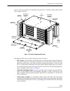
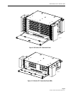
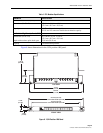
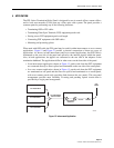
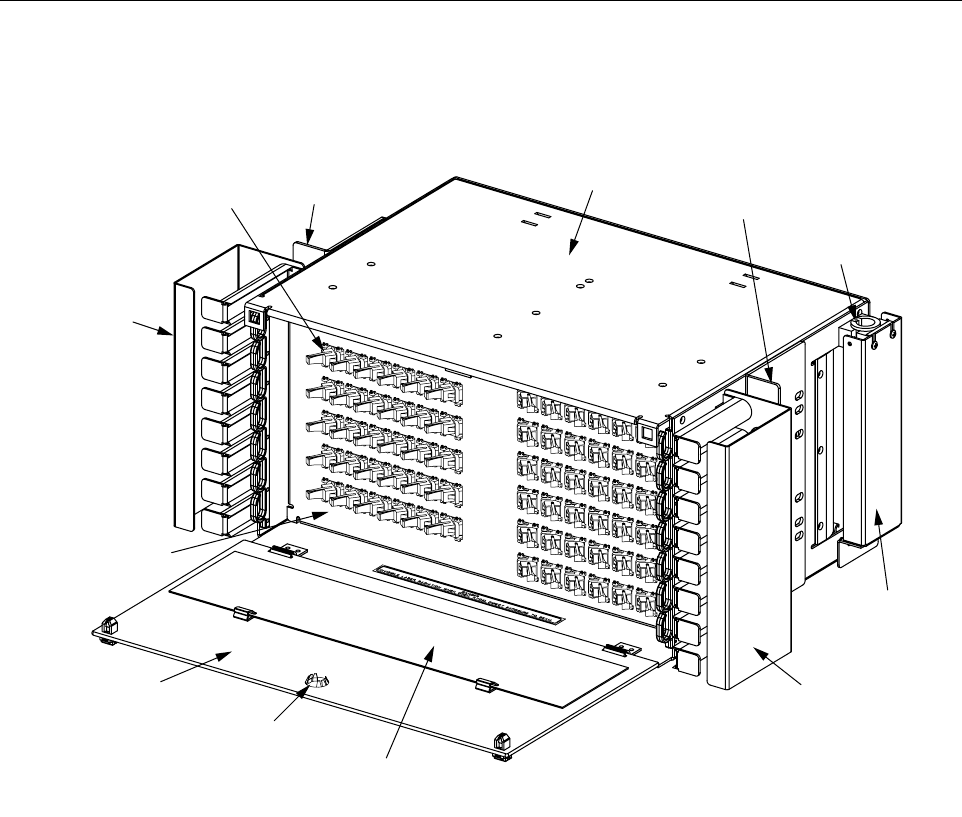
Figure 1 shows an example of a termination only panel, the 72 position model. Other models
have analogous features.
Figure 1. 72 Position Termination Only Panel
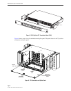
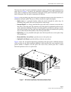
The features called out are as follows (from top center clockwise):
• FPL Chassis—is the boxlike, solid metal frame on which the panel is built. The chassis
shown is 8.7 inches (22.1 cm) high, 16.4 inches (41.7 cm) wide, and 12.0 inches (30.5 cm)
deep. This same chassis is also used for the 48 and 96 position panels, as well as for the
48, 72, and 96 position termination and splice panels. Shorter-height chassis are used for
the 12 and 24 position panels and a deeper chassis is used for the 144 position high density
panel. For details, refer to Table 1 on Page 8.
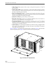
• Adjustable Mounting Bracket—(one on each side) can be oriented to provide either 19-
inch or 23-inch WECO or EIA rack mounting with either a 4-inch or 5-inch recess. The
panel is shipped with the mounting brackets positioned for installation in a 19-inch rack
with a 5-inch recess.
• Cable Clamp Assembly—is a kit used to clamp a cable to the panel. Two cable clamp
assemblies are provided with every FPL panel. Each clamp can accommodate a maximum
cable diameter of 0.80 inch (2.03 cm). A grounding lug is included with each cable clamp
for use if needed.
4
2
4
8
5
4
6
0
6
6
7
2
4
1
4
7
5
3
5
9
6
5
7
1
4
0
4
6
5
2
5
8
6
4
7
0
3
9
4
5
5
1
5
7
6
3
6
9
3
8
4
4
5
0
5
6
6
2
6
8
4
2
4
8
5
4
6
0
6
6
7
2
1
2
1
8
2
4
3
0
3
6
6
1
1
1
7
2
3
2
9
3
5
5
1
0
1
6
2
2
2
8
3
4
4
9
1
5
2
1
2
7
3
3
3
8
1
4
2
0
2
6
3
2
2
17816-A
FPL
CHASSIS
TERMINATION
BULKHEAD
ANGLED
ADAPTERS
PATCH CORD
DESIGNATION
CARD
VERTICAL
CABLE GUIDE
VERTICAL
CABLE GUIDE
ADJUSTABLE
MOUNTING
BRACKET
ADJUSTABLE
MOUNTING
BRACKET
REMOVABLE
FRONT DOOR
OPTIONAL
LOCK MOUNT
CABLE CLAMP
ASSEMBLY
CABLE
CLAMP
COVER