


ADCP-90-328 • Issue 2 • November 2005
Page 27
© 2005, ADC Telecommunications, Inc.
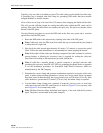
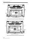
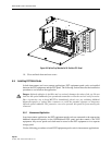
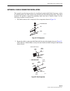
Figure 29. Routing Bundles into Splice Tray
7. Mark each buffer tube and pigtail to indicate the attachment point to the splice tray. Make
sure approximately 2 feet (61 cm) of fiber are left beyond the attachment point for
splicing.
8. Remove the splice tray from the FPL panel and uncoil the bundles from the radius limiters.
9. Beginning at the points marked in step 7, remove the buffer tubes and pigtail jackets to
expose the optical fibers. Clean fibers as recommended by cable manufacturer.
10. Secure the cable subunits and pigtails to the splice tray using tie wraps. The tie wraps
should be tight enough to secure the pigtail jackets and cable subunits but should not pinch
the fibers inside.
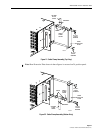
11. Complete each splice according to local splicing practice. Note that the numbered tag that
is attached to each pigtail corresponds to the number on the bulkhead connector plate.
12. Carefully secure each completed splice to the splice chip on the inside of the splice tray.
13. When all splices are complete, place the clear plastic cover over the splice tray to protect
the finished splices.
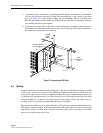
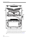
14. Coil up the bundles around the radius limiters (in the same direction as coiled in step 5)
and place the splice tray on the bottom of the FPL panel.
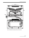
15. Secure the splice tray(s) to the bottom of the FPL panel using the rubber strap provided.
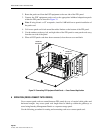
An example of a splice tray mounted in a FPL panel is shown in Figure 30.
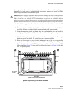
16. Record all terminations on the front designation cards as required by local practice.
17. Repeat steps 4 through 16 for the next splice tray, if any remains. Continue until all the
splice trays have been installed.
2776-A
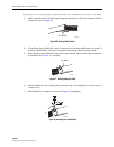
SECURE PIGTAILS AND BUFFER TUBES
TO SPLICE TRAY WITH TIE WRAPS
BUFFER TUBES