


ADCP-90-328 • Issue 2 • November 2005
Page 22
© 2005, ADC Telecommunications, Inc.
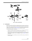
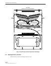
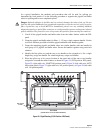
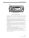
5. A grounding lug is provided for grounding metallic sheaths and metallic core members.
Use the nut and screw provided to fasten the grounding lug to the chassis at the point
shown in Figure 23. If the sheath bonding kit was installed, connect a bonding wire
between the connector stud and the lug. If the cable has a metallic core member, insert the
core member into the lug and tighten.
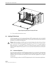
6. If splicing will not be done at this time, coil the buffer tubes around the radius limiters on
the bottom of the FPL panel and close the rear cover. If splicing will be done immediately,
proceed to the section that covers splicing.
Figure 23. Grounding the OSP Cable
5.5 Splicing
If you are installing a termination and splicing panel, and have just finished installing your OSP
or IFC cable, you can now proceed to the splicing procedure provided in this section. You will
be doing one splice tray at a time to completion, then going on to complete the next splice tray
(if the panel has more than one). For each splice tray, you will assign paired fibers and cable
subunits bundles of 12, measure for correct service loop length, remove the splice tray to a
working surface for splicing, and return the splice tray to the panel.
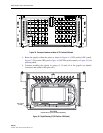
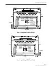
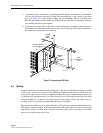
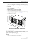
The purpose of a splice tray is to protect the splices. The splice tray mounts on the bottom of the
FPL panel, within the chassis in the mid-size models and on the splice area access door in the
high density model. A rubber strap is used to secure the splice tray to the bottom of the FPL
panel or to the splice area access door.
6
0
6
6
7
2
5
9
6
5
7
1
5
8
6
4
7
0
5
7
6
3
6
9
5
6
6
2
6
8
6
0
6
6
7
2
17830-A
REAR
PROTECTIVE
PLATE
GROUNDING
LUG
OUTSIDE
PLANT
CABLE
BONDING
WIRE
SHEATH BONDING
KIT CONNECTOR