


ADCP-90-328 • Issue 2 • November 2005
Page 23
© 2005, ADC Telecommunications, Inc.
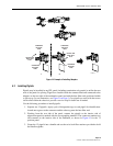
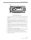
In a typical installation, the methods and procedures that will be used for splicing are
determined by local practice. Use the following procedure to organize the pigtails and buffer
tubes for splicing and to store completed splices:
1. Uncoil all the pigtail bundles and buffer tubes from the radius limiters within the FPL
panel.
2. Group the pigtails and buffer tubes for fibers 1 - 12 into a single common bundle. Use the
twist-lock retainers provided to hold the pigtail and buffer tube bundle together.
3. Group the remaining pigtails and buffer tubes into similar bundles with one bundle for
each group of 12 pigtails and buffer tubes. Secure the bundles together using twist-lock
retainers.
4. Identify the first splice tray and the one or two bundles to be assigned to it. For a single
height tray, assign one bundle. For a dual height tray, assign two bundles.
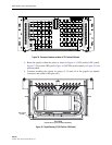
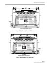
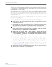
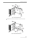
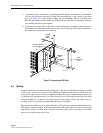
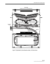
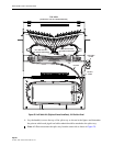
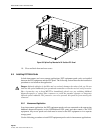
5. Place the splice tray in its correct location in the panel and coil the one or two bundles
assigned to it around the radius limiters as shown in Figure 24 (12/24 position 1RU panel),
Figure 25 (right cable exit, 24/48/72/96 position panel), Figure 26 (left cable exit, 48/72/
96 position panel), Figure 27 (right cable exit, 144 position panel), or Figure 28 (left cable
exit, 144 position panel).
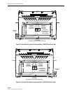
Figure 24. Pigtail Routing (12/24 Position 1RU Panel)
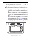
Danger: Infrared radiation is invisible and can seriously damage the retina of the eye. Do not
look into the optical bulkhead of an operational transmitter or into the receiver end of an active
fiber. A protective cap or hood MUST be immediately placed over any radiating bulkhead
adapter/receptacle or optical fiber connector to avoid potential exposure to dangerous infrared
optical radiation. The protective cover also prevents dirt particles from entering the connector.
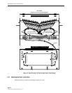
TOP VIEW
(SHOWN WITH TOP OF CHASSIS REMOVED)
OSP CABLE
CLAMP
20961-A