


ADCP-90-328 • Issue 2 • November 2005
Page 4
© 2005, ADC Telecommunications, Inc.
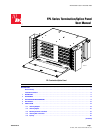
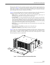
• Cable Clamp Cover—protects cable at entry to the panel (not present on 12 and 24
position panels).
• Vertical Cable Guide—(one on each side) is a metal cable retainer designed to provide
cable management by confining and directing patch cords to and from the panel and along
the frame on which the panel is installed.
• Patch Cord Designation Card—is a laminated card fastened to the inside of the panel
front door. The designation card is used to record the near-end and far-end termination
locations of each patch cord installed on the panel.
• Optional Lock Mount—provides ability to lock front door.
• Removable Front Door—protects the termination bulkhead and can be removed to
provide access to the bulkhead for connecting patch cords.
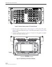
• Termination Bulkhead—provides a location for connecting patch cords. The bulkhead
shown has 72 holes for 72 adapters. Other bulkheads for the chassis size shown provide 48
or 96 locations for mounting connectors.
• Angled Adapters—are pass-through receptacles for connectors. They are angled to either
left or right to hold terminated fibers at an angle with respect to the bulkhead. The purpose
of the angle is prevent fiber bend.
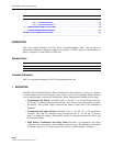
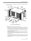
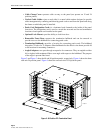
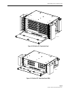
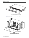
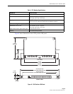
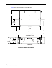
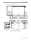
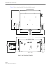
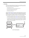
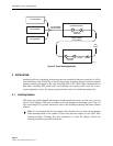
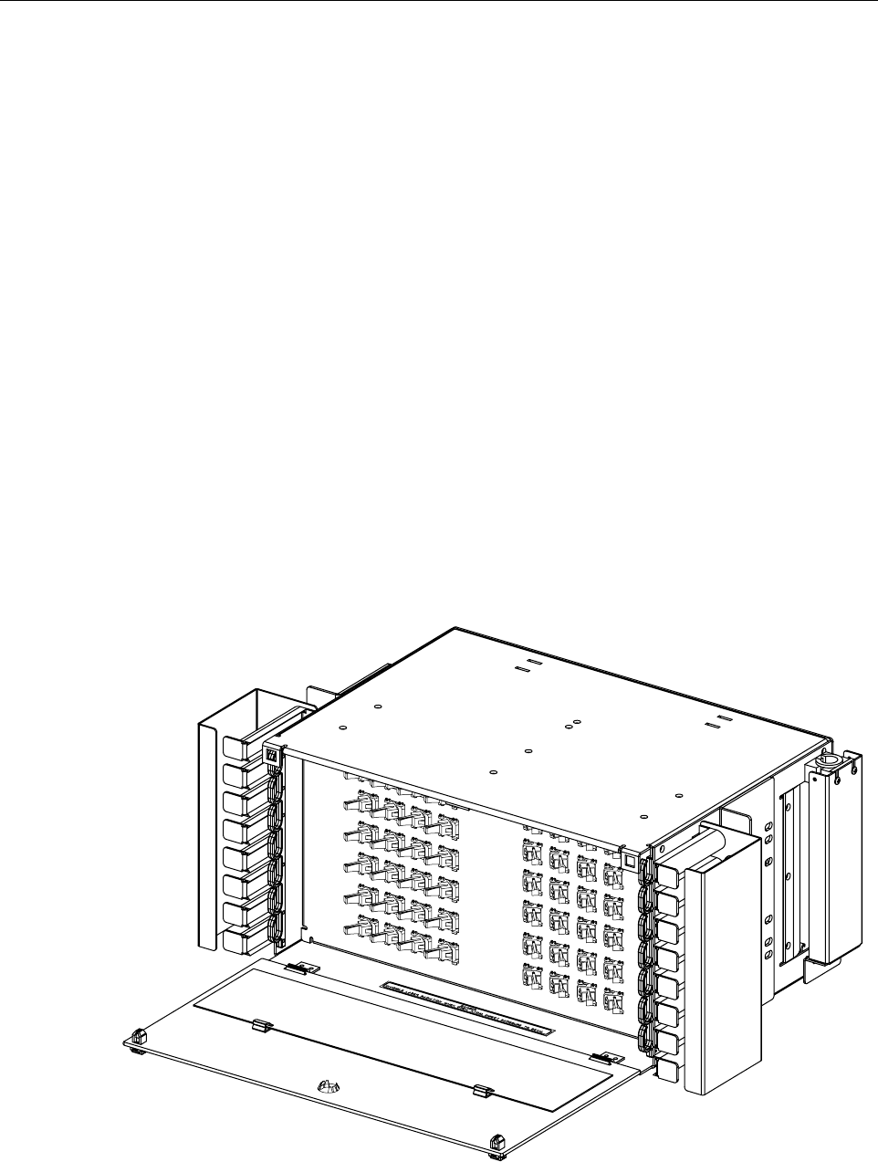
Figure 2 and Figure 3 show the 48 and 96 position panels, respectively. Figure 4 shows the three
rack unit 24 position panel. Figure 5 shows the one rack unit 12/24 position panel.
Figure 2. 48 Position FPL Termination Panel
17808-A
0
6
1
2
1
8
2
4
0
5
1
1
1
7
2
3
0
4
1
0
1
6
2
2
0
3
0
9
1
5
2
1
0
2
0
8
1
4
2
0
0
1
0
7
1
3
1
9
3
0
3
6
4
2
4
8
2
9
3
5
4
1
4
7
2
8
3
4
4
0
4
6
2
7
3
3
3
9
4
5
2
6
3
2
3
8
4
4
2
5
3
1
3
7
4
3