


ADCP-90-328 • Issue 2 • November 2005
Page 26
© 2005, ADC Telecommunications, Inc.
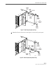
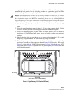
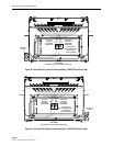
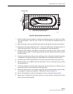
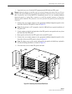
Figure 28. Left Cable Exit (Right as Viewed from Rear),144 Position Panel
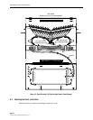
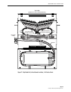
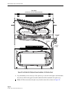
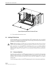
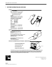
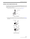
6. Lay the bundle(s) across the top of the splice tray as shown in the figures and determine
the point at which each pigtail and cable subunit should be attached to the splice tray.
Note: All fibers must enter the splice tray from the same side as shown in Figure 29.
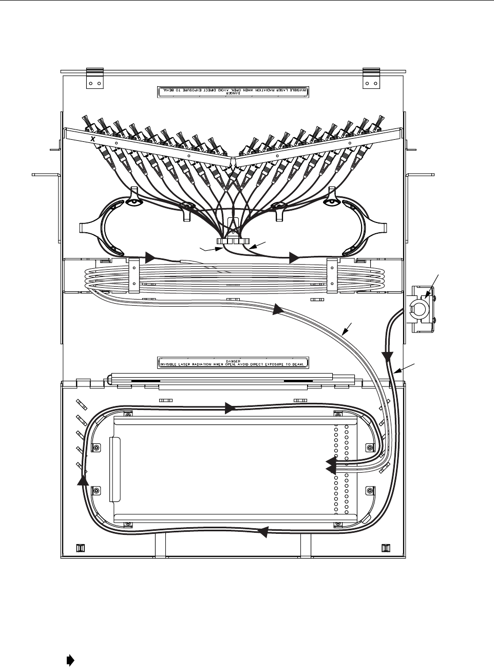
TOP VIEW
(SHOWN WITH TOP OF CHASSIS REMOVED)
OSP CABLE
CLAMP
BUFFER
TUBES
PIGTAILS
17918-A
RIGHT SIDE PIGTAILS
(AS VIEWED FROM REAR)
LEFT SIDE PIGTAILS
(AS VIEWED FROM REAR)