


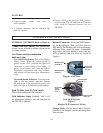

External Intercom Switch, Level Control,
and indicator: This switch enables the wired
intercom interface when “IN”, and disables it
when “OUT”. For RTS intercoms, the “IN”
position is channel 1 and the “OUT” position
is channel 2. A screwdriver adjustable control
is provided to control the input level of the
wired intercom.
Auxiliary Audio Enable Switch, Level Con-
trol, and Indicator: The switch enables and
disables the Auxiliary interface when “IN”
and “OUT”, respectively. The function of the
level control here is the same as that described
for the intercom.
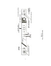
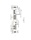
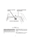
REAR PANEL (Refer to Figure 4)
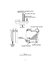
Transmit and Receive Antenna Connec-
tors:
Attach 5/8-wave antennas (supplied) to these
connectors; Antenna color should match the
“color dot.”
Transmit Switch: Slide switch that allows the
operator to select one of three transmit modes.
In the “OFF” position, the transmitter is al-
ways off. This mode may be used if the base is
functioning solely as a monitor. In the
“CONT” position, the transmitter is always
on. This continuous mode is recommended
over the “REMOTE” mode. In the “RE-
MOTE” position, the transmitter is enabled
only when one or more portables are active.
Headset Microphone Select Switch: This
switch allows the user to select either an
Electret or Dynamic microphone.
Intercom Connectors: Connections to inter-
face the BTR-300 with a wired intercom sys-
tem.
Auxiliary Output/Input Connectors: Can be
used for 2-way (four wire) input and output to
the BTR-300 or as a simplex input or output.
Typical uses are 4 wire intercom’s, tape re-
corders, public address inputs or outputs.
Power Jack: For external AC supply adaptor
(supplied).
Speaker Jack: Allows the use of an external
monitor if desired. An 8 ohm speaker is rec-
ommended.
Speaker Volume Control: Screwdriver ad-
justable. Adjust clockwise to increase speaker
volume or counterclockwise to decrease
speaker volume.
NOTE: Leave setting counterclockwise if no
speaker is attached.
-6-