


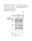

EQUIPMENT SET-UP
BTR-300 SET-UP
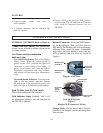
UNPACKING
Unpack your BTR-300 and TR-300 System. If
there are any damages or shortages, refer to
the “Warranty Service Information” section in
this manual.
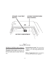
INTERNAL INTERCOM SWITCHES
The BTR-300 has internal switches that allow
it to accommodate intercom systems other
than what it was set to interface with when
manufactured. Product No. 71276XXXX is set
for Telex Audio Com and similar systems.
Product No. 71280XXXX is set for RTS 2
wire and similar systems. Units originally set
for Telex may be set to RTS and vice versa.
Both models may be set to interface with
Clearcom, and 4 wire RTS/McCurdy matrix
type systems. The following paragraphs ex-
plain how to change the switches if necessary.
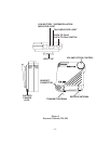
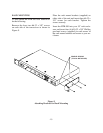
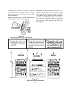
Remove Cover: Remove the cover screws
(13) and lift off the cover.
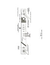
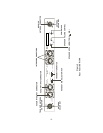
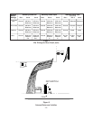
DIP Switch: See Figure 8 and Table 1. Set the
DIP switch as shown in the table.
High/Low Switch: See Figure 8 and Table 2.
Set the high/low switch as shown in the table.
Intercom Switch: See Figure 8 and Table 2. Set
the switch to 2 wire for all 2 wire systems. Set
the switch to 4 wire if the BTR is to be con-
nected to a balanced 4 wire intercom system
through the Auxiliary input and output jacks.
Note: Do not connect both 4 wire and 2 wire sys-
tems at the same time. Loud feedback may result.
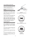
Replace Cover: Carefully align the cover and
replace the screws.
INTERCOM JACK WIRING
CONFIGURATIONS
See Table 3 for the wiring of the intercom and
auxiliary jacks.
Table 1
Table 2
-13-
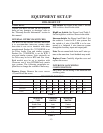
DIP SWITCH POSITION
123456789
Telex Audiocom ON ON OFF ON OFF ON OFF OFF ON
RTS 2 wire OFF OFF ON OFF ON OFF ON ON OFF
Clearcom ON OFF ON ON OFF OFF OFF ON ON
4 Wire N/A N/A N/A N/A N/A N/A N/A N/A N/A
INTERCOM LOW/HIGH INTERCOM
TYPE SWITCH SWITCH
Telex
Audio Com Low 2 wire
RTS High 2 wire
Clearcom Low 2 wire
4 wire N/A 4 wire