


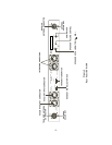

CONTROLS and CONNECTIONS
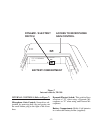
FRONT PANEL (Refer to Figure 3)
Power ON/OFF Switch: Push this switch
once to turn power ON; push it again to turn
the power OFF.
Power ON Indicator: The Power ON light is
illuminated when the Power ON/OFF Switch
is pushed in the ON Position.
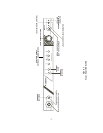
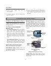
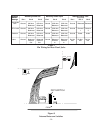
Local Headset Connector: Four pin XLR
Connector for Input/Output (plug for Telex
units and jack for RTS units). The headset
jack will accept many Telex model headsets.
Compatible with other intercom headsets with
four pin XLR connectors that are wired as
shown in Figure 2.
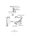
Figure 2
Headset XLR Connector Wiring
Local Headset Volume: Adjusts volume to
Local Headset. DOES NOT AFFECT MI-
CROPHONE GAIN.
Mic On-Push-to-Talk/Lock-to-Talk Switch:
Enables the local headset microphone audio
function.
NOTE: DOES NOT control base station RF
transmit.
Local Push-to-Talk Indicator: Will be illu-
minated whenever the talk function is on.
Local Microphone Gain Control and
Overmodulation Indicator: A screwdriver
adjustable control is provided to control the
input level of the local headset mic. This input
is protected from overloads by means of a
gain compressor whose operation is signaled
by the gain light indicator.
Portable Enable Switches and Indicators:
When in the “IN” position, the Enable
switches allow the user of the corresponding
portable unit to be heard by others connected
to the system. When in the “OUT” position,
the respective portable will be muted, but this
portable will still be able to hear all other se-
lected remotes and interfaces. The indicators
(Portable Transmit On) normally show the
presence of a portable transceiver in use on
the channel corresponding to that indicator.
-5-
BALANCED
AUDIO OUT
(3 AND 4)
MICROPHONE
GROUND (1)
MICROPHONE
AUDIO (2)
1
2
3
4
BALANCED
A
UDIO OUT
(3 AND 4)
MICROPHONE
GROUND (1)
MICROPHON
E
AUDIO (2)
4
3
2
1
Plug for Telex Unit
Jack for RTS Unit