


FEATURES
· Lightweight, small size and is
self-contained.
· 2 separate antennas, one for transmit, the
other for receive.
· Push-to-Talk with Lock-to-Talk feature
switch for the TR-300 and Push-to-Transmit
with Lock-to-Transmit feature for the
TR-300P.
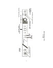
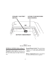
CONTROLS AND CONNECTIONS
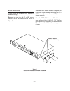
EXTERNAL CONTROLS (Refer to Figure 6)
Volume OFF/ON Control: This thumbwheel
control serves as both an off/on switch and as
a volume control.
Low Battery and Overmodulation
Indicator Light:
Low Battery Indicator: Part of the battery
check circuit. When the power switch is
placed in the “ON” position the light will
flash one or more times if the battery is
good. A poor battery will cause the light to
illuminate continuously and a bad or unus-
able battery will not cause any illumination
at all.
Overmodulation Indicator: Uses the same
light as the low battery indicator. During
the talk mode, if the microphone gain is too
high, the light will illuminate when talking.
Push-To-Talk, Lock-To-Talk Switch:
This switch enables the talk function.
Talk Indicator Light: (Labeled “talk”) will
be illuminated whenever the talk function on
the TR-300 is enabled.
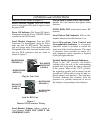
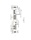
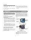
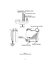
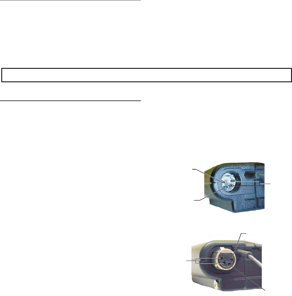
Headset Connector: A four pin XLR connec-
tor for Input/Output. (Plug for Telex, Jack for
RTS units). The headset jack will accept many
different Telex model headsets. Compatible
with other intercom headsets with four pin
XLR connectors that are wired as shown in
Figure 5.
Plug for Telex Units
Jack for RTS Units
Figure 5
Headset XLR Connector Wiring
Charge Jack: Allows nickel-metal hydride
batteries to be charged without removing them
from the unit.
-10-
BALANCED
AUDIO OUT
(3 and 4)
MICROPHONE
GROUND (1)
MICROPHONE
AUDIO (2)
MICROPHONE
GROUND (1)
MICROPHONE
AUDIO (2)
BALANCED
AUDIO
OUTPUT
(3 and 4)