


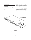
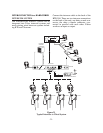
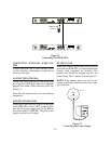
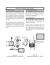
Figure 22
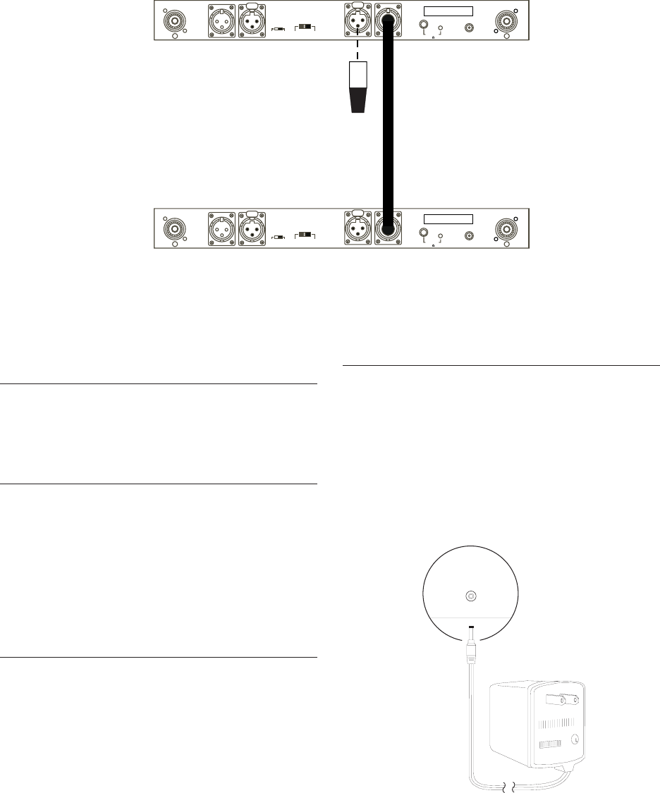
Connecting Two BTR-300’s
CONNECTING AUXILIARY AUDIO SYS-
TEM
Connect the BTR-300 to your auxiliary audio
via the Auxiliary input/output receptacles on
the rear of the unit.
CONNECTING BTR-300’s
Connect the first BTR-300 to other BTR-300s
by using short XLR type cables (not supplied)
plugged into either of the intercom jacks. See
Figure 22.
Note that the stations need to be on different
frequencies.
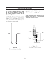
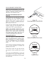
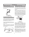
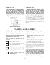
POWER CONNECTION
Insure the Power ON/OFF Switch on the front
of the BTR-300 is in the “OFF” position. Con-
nect the AC power supply cord to the BTR at
the socket labeled “POWER”. Plug the power
supply unit into an AC outlet.
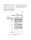
DUMMY LOAD
In the case where a wired intercom will not be
used with the BTR-300, it is important that the
dummy load (supplied) be installed. The
dummy load should be plugged into the “In-
tercom Loop-Thru” connector. See Figure 22.
NOTE: If the dummy load is not used an an-
noying squeal may result that may cause dam-
age to the ears.
Figure 23
Connecting the Power Supply
-22-
PUSH
PUSH
Transmit
Antenna
Auxiliary
Audio Output
Auxiliary
Audio Input
Headset Mic
Dyn
Elt
Off
Remote
Cont
Loop Thru
Intercom
Intercom
Loop-Thru
Speaker
Power
AC/DC 12V
700 mA
Transmit
Receive
Antenna
Intercom
Loop-Thru
Telex Communications Inc.
BTR-300
MADE IN U.S.A.
Volum e
8
PUSH
PUSH
Transmit
Antenna
Auxiliary
Audio Output
Auxiliary
Audio Input
Headset Mic
Dyn
Elt
Off
Remote
Cont
Loop Thru
Intercom
Intercom
Loop-Thru
Speaker
Power
AC/DC 12V
700 mA
Transmit
Receive
Antenna
Intercom
Loop-Thru
Telex Communications Inc.
BTR-300
MADE IN U.S.A.
Volum e
8
DUMMY LOAD
(IF USED)
U
AC/DC 12 OV 700mA
POWER
BTR 300