


Dual Lis ten Func tion al ity
The base sta tions's main au dio board has the op tion of plac ing
ad di tional parts to en able dual lis ten. Dual lis ten al lows the
mix ing of the in ter com chan nels. The mix ing will oc cur lo --
cally, within the base sta tion, and is only heard on that base
sta tion's beltpacks. The user will have the abil ity to en able/dis --
able the mix of I/C A into I/C B or vise versa. If you have
TR-825 beltpacks, there is no need to in stall this base op tion.
The level of the mix can be controlled at the TR-825 via the
two vol ume con trols.
They will also have the abil ity to con trol the level of the mix
(-4 dB to -24 dB down from main chan nel). Re moving two
sur face mount re sis tors and in stall ing two SPDT switches and
two po ten ti om e ter en ables dual lis ten. The parts to be in stalled
are shown in Ta ble 1. The two re sis tors on the board to be re --
moved are in Ta ble 2.
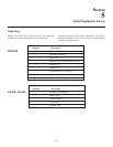
Ta ble 1
Parts to be In stalled by User to En able Dual Lis ten
Ta ble 2
Parts to be Re moved by User to En able Dual Lis ten
The listed man u fac tures and part num bers in Ta ble 1 are those
that the au dio board was laid out for and thus the hole pat tern
used. Sev eral of these parts may be found at Digi-Key and
other dis trib u tors. Trim the leads on the parts so they can not
hit the metal case. Lo ca tions to place these com po nents are
pro vided on au dio board part num ber 750608.
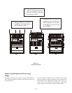
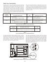
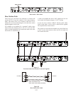
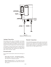
The au dio board part num ber is lo cated on the lower left hand
side of the board if fac ing the front of the unit. The lo ca tions
where the com po nents can be in stalled are on the up per right
hand side of the board. See Fig ure 22 for the lo ca tions. Board
part num ber 750541 does not have lo ca tions to place com po --
nents, how ever, mod i fi ca tion doc u ments may be ob tained
from Telex Com mu ni ca tions for those who wish to mod ify
older au dio boards for dual lis ten.
Fig ure 22
Au dio Board Part Num ber and Dual Lis ten Com po nent Lo ca tions
5-8
Board
Des ig na tor De scrip tion and Func tion Value Man u fac turers, Part No.
VR5, VR6 Po ten ti om e ters 20kW - 25kW Bourns, 3309P-1-203
VR5 = Con trols I/C A into I/C B Mix CTS, U262R253B
VR6 = Con trols I/C B into I/C A Mix Piher, PT10LV10-203A2020
S6, S7 Switches SPDT E-Switch, 500ASSP1M2RE
S6 = En able/Dis able I/C A into I/C B Mix E-Switch, EG1218
S7 = En able/Dis able I/C B into I/C A Mix Alcoswitch, TSS11DGPC
Board
Des ig na tor De scrip tion and Func tion Value
R295 Re sis tor, De fault if mix com po nents not in stalled 10k
R296 Re sis tor, De fault if mix com po nents not in stalled 10k
FRONT
BACK
B INTO A
MIX
B INTO A
MIX
OFFOFF
ONONONON
IF PARTS INSTALLED
REMOVE R296
S7S7
S6S6
R296R296
R298R298
VR6VR6
MIX
LEVEL
MIX
LEVEL
OFFOFF
ONONONON
IF PARTS INSTALLED
REMOVE R295
R295R295
R297R297
VR5VR5
MIX
LEVEL
MIX
LEVEL
A INTO B
MIX
A INTO B
MIX
B INTO A
MIX
B INTO A
MIX
OFFOFF
ONONONON
IF PARTS INSTALLED
REMOVE R296
S7S7
S6S6
R296R296
R298R298
VR6VR6
MIX
LEVEL
MIX
LEVEL
OFFOFF
ONONONON
IF PARTS INSTALLED
REMOVE R295
R295R295
R297R297
VR5VR5
MIX
LEVEL
MIX
LEVEL
A INTO B
MIX
A INTO B
MIX
750608 REV X
879416- 1 REV J
750608 REV X
879416- 1 REV J