


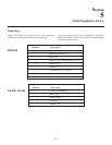
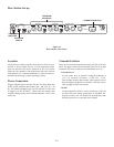
Con trols and Con nec tions - Rear Panel
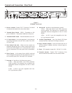
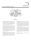
Fig ure 8
TR-825 Rear Panel/Con nec tor/An tennas
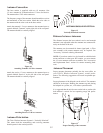
1. [MENU] and [SET] but tons – Used to se lect menus and
set op tions on the LCD.
2. LCD (Liq uid Crys tal Dis play)
3. [UP] and [DOWN] but tons – Used to se lect beltpack op -
tions on the LCD.
4. Mi cro phone Gain – Ad justs the head set’s mi cro phone
gain. Ad just so that the BAT/OM LED will flash at the be -
gin ning of most words at nor mal speech lev els
5. Push-to-Talk/Push-to-Transmit Switch –
Push-to-Talk (PT TALK) – The trans mit ter is al ways
on. No au dio sent un less the talk switch, WTA or SA
but ton pressed. Rec om mended po si tion.
Push-to-Transmit (PT TX) - The trans mit ter and au dio
path are off ex cept when the talk switch, WTA or SA
but ton is pressed.
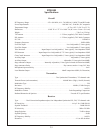
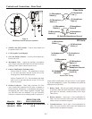
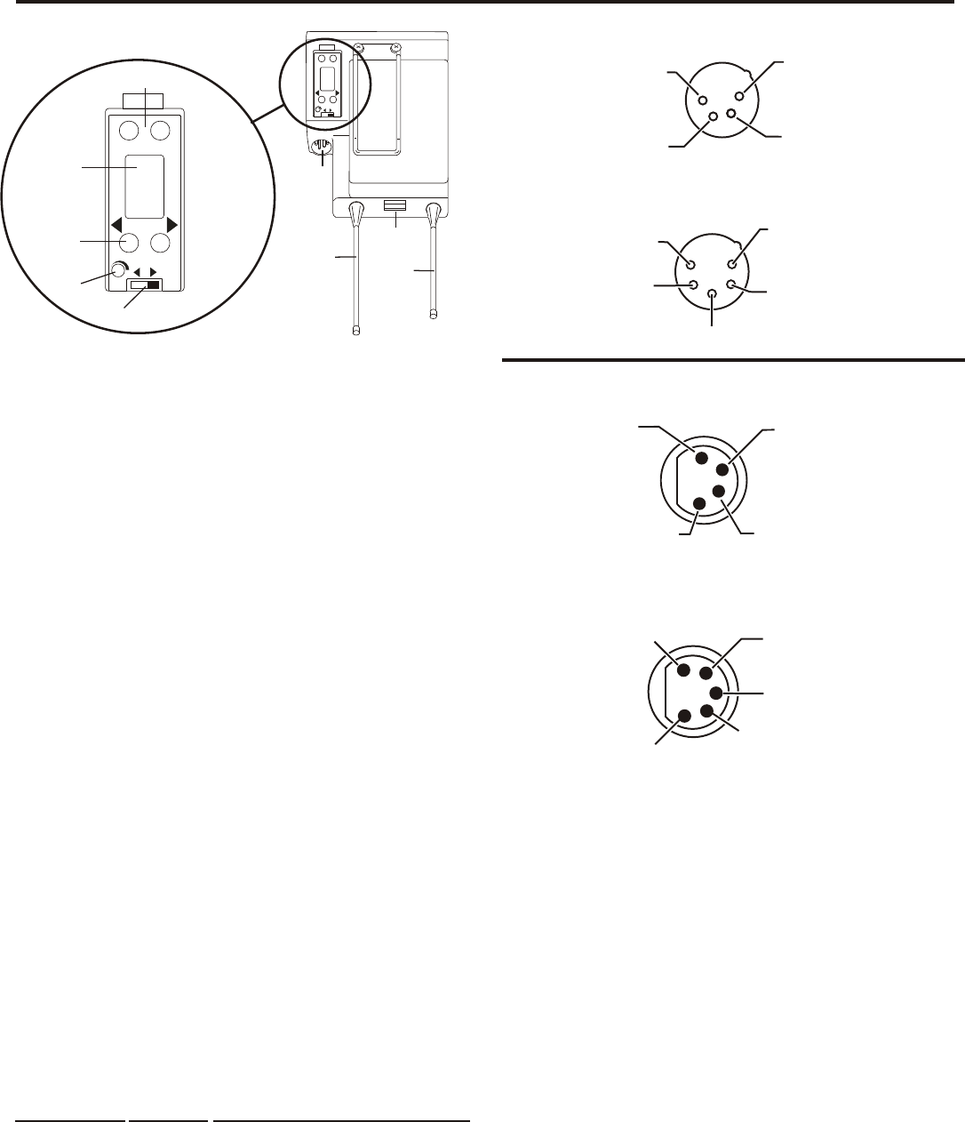
6. Head set Con nec tor – Male XLR con nec tor for Telex
units, Fe male XLR con nec tor for RTS units. A dy namic or
electret head set mi cro phone is au to mat i cally de tected by
the beltpack and a bias volt age sup plied if needed. Four
pin Telex/RTS units are mon au ral. Five pin Telex/RTS
units have a soft ware set-up which grounds or opens pin 3.
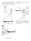
Fig ure 9
Head set Jack Wir ing
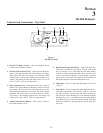
Sin gle sided 5-pin head sets will only re ceive A or B, de pend --
ing on how head phone is wired. These head sets must have the
beltpack set for [Ab SEP]
7. Bat tery Latch – Press down to en able the bat tery pack to
be re leased. While the latch is held down, slide the bat tery
pack about 1/8 inch back, to ward the latch, un til it stops.
Then lift out.
8. Re ceive An tenna – Screw type ¼-wave re place able an -
tenna. The color dot on the screw end of the an tenna must
match color dot on an tenna re cep ta cle.
9. Trans mit An tenna – Screw type ¼-wave re place able an -
tenna. The color dot on the screw end of the an tenna must
match color dot on an tenna re cep ta cle.
4-2
(1) Microphone
Shield (-)
(2) Microphone
Audio (+)
(4) Headphone
Low (-)
(3) Headphone
High (+)
MENU
SET
MI
C
P
T
T
X
P
T
T
AL
K
6
6
7
7
8
8
9
9
MENU
SET
MIC
PT
TX
P
T
T
ALK
22
11
33
44
55
(1) Microphone
Shield (-)
(3) Switched
Headphone Ground
(2) Microphone
Audio (+)
(4) Headphone
(Audio A)
(5) Headphone
(Audio B)
(1) Microphone
Shield (-)
(4) Headphone
Low (-)
(3) Headphone
High (+)
(2) Microphone
Audio (+)
RTS Units
Telex Units
(1) Microphone
Shield (-)
(2) Microphone
Audio (+)
(5) Headphone
Audio B
(4) Headphone
Audio A
(3) Switched Headphone Ground
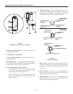
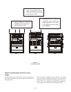
Menu Set
[ Ab SEP ]
[ Ab Add ]
PIN 3
GND
OPEN
RESULT ON 5-PIN
DUAL HEADPHONE
A in one side, B in other side
A + B