


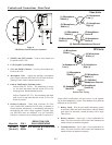

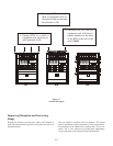
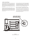
In ter nal Trans mit Switches
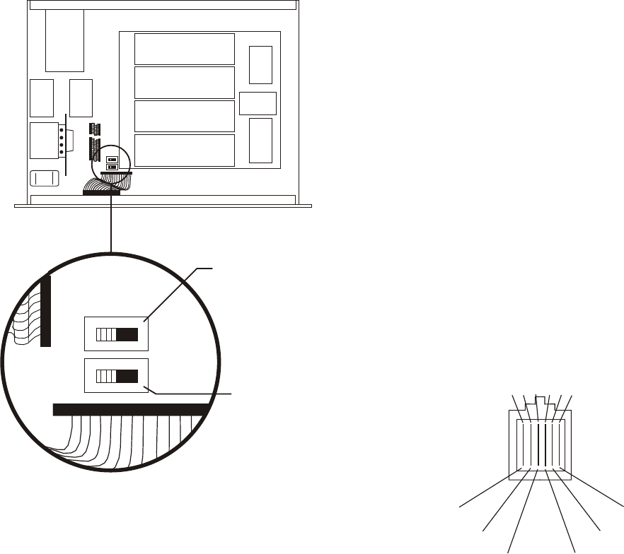
In ter nal to the BTR-800 are two trans mit switches which en --
able a user to turn on or off the two trans mit ters in di vid u ally.
See Fig ure 19 for the lo ca tion. The top cover of the base sta --
tion must be re moved for ac cess. The switch clos est to the
front panel con trols trans mit ter 1 (au dio chan nel A). The
switch be hind that is trans mit ter 2 (au dio chan nel B). The de --
fault switch po si tion is to the left if you are fac ing the front of
the base sta tion. This is the “ON” po si tion for the trans mit ters.
In the nor mal use of the BTR-800, there is no need to ac cess
these switches. They are used to test the trans mit ters in di vid u --
ally at the fac tory.
Fig ure 19
In ter nal Trans mit Switches
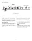
In ter com Switch
The RadioCom® wire less sys tem can be in ter faced to RTS,
TW, Audiocom® (Telex), Clear-Com®
,
RTS ma trix and other
in ter com (I/C) sys tems. Set the In ter com switch on the rear of
the unit to the ap pro pri ate sys tem and con nect the sys tem to
the base sta tion. The two in ter com chan nels on the rear of the
base sta tion have loop-thru male and fe male XLR con nec tions
for two-wire sys tems and RJ-11 type jacks for four-wire sys --
tems.
This switch only af fects the two-wire in ter com sys tems. The
func tions of the I/C XLRs change de pend ing on the in ter com
se lected. Please see Sec tion 12 for pinout in for ma tion of the
dif fer ent two-wire in ter com sys tems.
In ter com In ter face
Telex (Audiocom®) and Clear-Com®
in ter com sys tems re --
quire one ca ble for in ter com A and one ca ble for in ter com B in
or der to in ter face two chan nels of in ter com to the base sta tion.
This in ter fac ing is done through the I/C A and B 3-pin XLR
con nec tors on the rear of the unit.
RTS TW in ter coms only need to con nect one 3-pin ca ble to
one of the four in ter com XLR con nec tors since two chan nels
of au dio are car ried on one ca ble. The in ter com switch par al --
lels the four XLR con nec tors when in RTS mode. RTS chan --
nel 1 is placed on in ter com A and RTS chan nel 2 is placed on
in ter com B as long as the RTS TW in put to the base sta tion is
wired as in Sec tion 12.
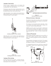
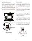
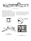
Four-wire in ter com sys tems re quire one ca ble for in ter com A
and one ca ble for in ter com B in or der to in ter face two chan --
nels of four-wire in ter com to the base sta tion. This in ter fac ing
is done through the I/C A and B RJ-11 type jacks on the rear
of the unit. See Fig ure 20 for the pinout of the RJ-11 jacks.
Fig ure 20
RJ-11 Type/ Four-wire Pinout
5-6
ON
ON
S3
OFF
S4
OFF
Transmitter 2
Transmitter 1
FRONT
BACKBACK
NC
AUDIO IN +
AUDIO OUT +
AUDIO OUT -
AUDIO IN -
NC
PIN 6 5 4 3 2 1