


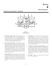

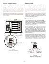
An tenna Con nec tion
The base sta tion is sup plied with two (2) an ten nas. One
1/2-wave an tenna for Trans mit and one 1/2-wave for Re ceive.
The an ten nas have TNC male con nec tors.
The fre quency range of the an ten nas should match the re ceiver
and trans mit ter of the base sta tion. Match the color code on
the an tenna with the color code on the base sta tion.
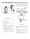
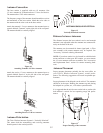
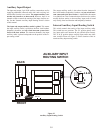
At tach the trans mit 1/2-wave an tenna to the an tenna in put re --
cep ta cle la beled “Trans mit” on the right side of the rear panel.
The an tenna should be ver ti cally aligned.
Fig ure 10
Attaching Trans mit 1/2-Wave An tenna
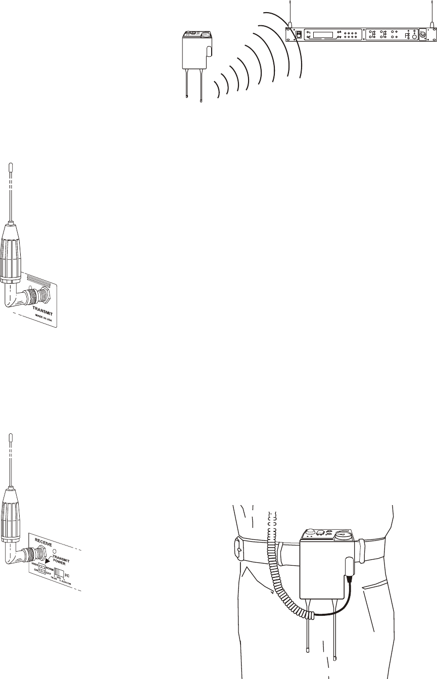
At tach the re ceive 1/2-wave an tenna to the an tenna in put re --
cep ta cle la beled “Re ceive” on the left side of the rear panel.
The an tenna should be ver ti cally aligned.
Fig ure 11
Attaching Re ceive 1/2-Wave An tenna
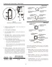
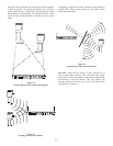
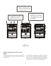
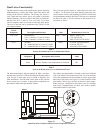
An tenna Po lar iza tion
The Telex Wire less In ter com Sys tem is “Ver ti cally Po lar ized”.
This means both the trans mit ting and re ceiv ing an ten nas
should op er ate in the ver ti cal po si tion.
Fig ure 12
Ver ti cally Po lar ized An tennas
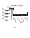
Dis tance be tween An tennas
The dis tance be tween the base sta tion’s re ceive and trans mit
an ten nas is not ad just able when the an ten nas are con nected di --
rectly on the back of the unit.
The an ten nas can be remoted for better sig nal path. A Telex
coax as sem bly with re mote an ten nas may be re quired. See
"Ac ces sory" sec tion fr or der ing information.
NOTE: If your base sta tion is to be lo cated in a shielded rack
mount en clo sure or other poor RF lo ca tion, you must re mote
the 1/2-wave an ten nas with coax as sem blies. See "Ac ces sories
and Re place ment Parts" sec tion for re mote mount ing hard --
ware.
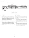
An tenna Place ment
Proper an tenna place ment prob a bly has the most ef fect on
your TELEX Wire less In ter com Sys tem’s over all per for --
mance. The fol low ing sug ges tions will re sult in op ti mum per --
for mance.
Proper place ment of the beltpack can be crit i cal. The an ten nas
should be in the open. Bending the an ten nas up and plac ing
the beltpack in a pocket, etc., will re duce sys tem dis tance.
It is sug gested that the unit be worn on the belt or pocket with
both an tenna’s ver ti cal for best op er at ing range and per for --
mance.
Fig ure 13
Proper Dress ing of the An tennas
5-2
T
e
l
e
x
W
T
A
A
B
O
F
F
B
A
T
/
O
M
T
A
L
K
R
a
d
i
o
C
o
m
T
R
-
8
0
0
T
M
VOL
SA
TALK
MIC GAIN
TALK/O.M.
VOLUME
SELECT
A
B
ON/O.M.
ON/OFF
IN
OUT
AUXILIARYINTERCOM B
2 WIRE
4 WIRE
SELECT
IN
OUT
2 WIRE
4 WIRE
SELECT
IN
OUT
INTERCOM A
PORTABLE STATION CONNECT
1 2
3
4
UP
DOWN
MENU
SET
RadioCom
ä
BTR-800
ClearScan
TM
COPY
ANTENNAS SHOULD BE VERTICAL
T
e
l
e
x
W
T
A
A
B
O
F
F
B
A
T
/
O
M
T
A
L
K
R
a
d
i
o
C
o
m
T
R
-
8
0
0
T
M
VOL
SA