


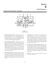

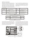
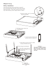

Base Sta tion Set-up
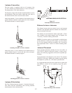
Lo ca tion
Lo cate the base sta tion with the front and rear of the unit ac --
ces si ble so that switches may be set and con nec tions made.
Place the trans mit and re ceive an ten nas on the base sta tion.
Make sure the an tenna’s color band match the color dot near
each an tenna. See “An tenna In for ma tion” sec tion for more in --
for ma tion on choos ing a proper op er at ing lo ca tion.
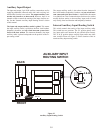
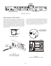
Power Con nec tion
Plug the sup plied power cord into the unit. The base sta tion has
an IEC power re cep ta cle that ac cepts 100 – 240 VAC, 50 – 60
Hz. The spe cific re cep ta cle type is an IEC 60320/C14. The cord
it ac cepts is an IEC 60320/C13. These cords are com mon and
avail able through many re tail hard ware/elec tronic stores if the
cord is lost.
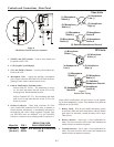
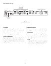
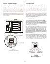
Trans mit Switches
There are two switches lo cated on the lower left side of the rear
panel. The up per switch sets the trans mit power lev els to high
or nor mal. The lower switch turns the trans mit ters on or off.
Trans mit Power
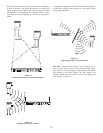
Set the power level to nor mal if us ing the beltpacks at
close to me dium dis tances (<200 feet, 161m,
line-of-sight) from the base sta tion. Set the power level to
high if us ing the beltpacks at a dis tance (>200 feet, 161m,
line-of-sight) from the base sta tion.
On/Off
Set the trans mit ter switch to on for nor mal use. In the off
po si tion both base sta tion trans mit ters are dis abled. Set --
ting the switch to off will dis able all the beltpacks from
hear ing any one else or even their own sidetone.
5-5
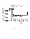
RECEIVE
HIGH
ON
NORM
OFF
TRANSMIT
POWER
I/C
TELEX CLEARCOM
RTS
BTR-800
FCC ID: B5DM514
CANADA 1321231218A
BASE STATION
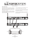
LINK
RELAY
CONTACT
INTERCOM A
2 WIRE
L
O
O
P
T
H
R
U
4 WIRE
INTERCOM B
2 WIRE
L
O
O
P
T
H
R
U
4 WIRE
AUXILIARY AUDIO
INPUT OUTPUT
STAGE ANNOUNCE
OUTPUT
POWER
100-240 VAC 50-60 Hz
TRANSMIT
MADE IN USA
PUSHPUSHPUSH
Telex
Telex Communications, Inc.
POWER CONNECTION
INTERCOM
SWITCH
TRANSMIT
SWITCHES
INTERCOM
INTERFACE
Fig ure 18
Base Sta tion - Rear Panel