


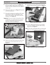
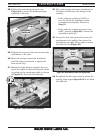

28. Tighten the arm clamp cap screw (see
Figure 20) to secure the deadman clamp
assembly to the arm.
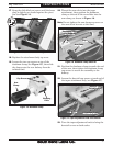
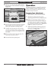
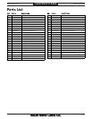
Figure 21. Taper attachment alignment.
!
29. Tighten the arm clevis hex nut to secure the
attachment to the arm.
30. Move the carriage toward the headstock
until the taper attachment is against the
front travel stop.
31. Mount the dial indicator magnetic base on
top of the saddle so that the indicator needle
is resting on the attachment table, as shown
in Figure 21, then zero the indicator.
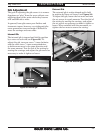
Arm Clamp
Cap Screw
Clevis
Hex Nut
Figure 20. Arm clamp cap screw and clevis hex nut.
32. Move the carriage and taper attachment to
the other end and note any change in the
reading.
— If the indicator reading is 0.025" or
less, the tilt of the attachment table
is considered acceptable. Proceed to
Step 35.
— If the indicator reading is greater than
0.025", proceed to Step 33 to correct the
attachment table tilt.
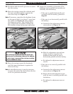
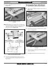
33. Loosen the four cap screws that secure the
attachment to the saddle, then rotate the
attachment assembly left or right to correct
the table tilt (see Figure 22).
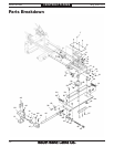
Figure 22. Attachment table tilt adjustment.
Rotate
Body
34. Re-tighten the four cap screws to secure the
setting, then repeat Steps 32–33 to re-check
the table tilt.
Mfg. Since 9/11 Model SB1263
-9-
INSTRUCTIONS