


24. Re-tighten both dovetail cap screws to secure
the zero setting.
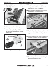
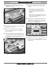
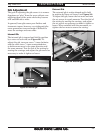
25. Move the carriage toward the tailstock until
the taper attachment body is against the
rear travel stop (see Figure 18).
Note: If necessary, reposition the deadman clamp
on the arm so that it is at least 1" away from
the saddle (see Figure 18) and re-tighten
the clamp cap screws. This “saddle safety
gap” will prevent the saddle crashing into
the deadman clamp during taper operations.
2 7. Inspect the assembly to determine if the
deadman arm is parallel horizontally and
vertically with the bedway.
— If the arm is parallel horizontally and
vertically with the bedway, proceed to
Step 26.
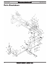
— If the arm is not horizontally parallel with
the bedway:
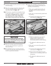
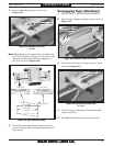
a. Loosen the four adjustment cam set
screws shown in Figure 19.
Figure 18. Saddle gap.
Complete Travel Without
Deadman Clamp Contact
1" Saddle
Safety Gap
Rear Travel Stop
b. Slide the adjustment cam and arm
clamp toward or away from the
deadman clamp until the arm is
horizontally parallel with the bedway.
c. Re-tighten the adjustment cam set
screws.
— If the arm is not vertically parallel with
the bedway:
a. Loosen the four adjustment cam set
screws shown in Figure 19.
b. Rotate the knurled adjustment cam
until the arm is vertically parallel with
the bedway.
c. Re-tighten the adjustment cam set
screws.
You will need to perform Step 25 each time
you secure the deadman clamp to the bedway
to cut a taper to prevent the carriage crashing
into the deadman clamp.
26. Move the carriage toward the headstock
until the taper attachment is against the
front travel stop.
Note: In the following step, it may be necessary
to rotate the arm so the clevis allows the arm
to tilt in a particular direction.
Figure 19. Adjustment cam set screws.
Adjustment
Cam
Adjustment Cam
Set Screws
-8-
Mfg. Since 9/11
Model SB1263
INSTRUCTIONS