5
System Configuration
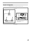
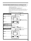
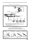
The figure below shows an example of the conference system.
System configuration
Conference hall
VU
I
O
POWER
PHONES
ON
OFF
MONITOR
MIN MAX
1
2
3
4
5
6
7
8
9
010
1
2
3
4
5
6
7
8
9
MONITOR
MIC/LINE 1 MIC/LINE 2
MIC/LIMIT
ON/OFF
DIRECT ACCESS
ON/OFF
SEAT ASIGN
START/END
D/C UNIT SP
010
1
2
3
4
5
6
7
8
9
010
1
2
3
4
5
6
7
8
9
010
1
2
3
4
5
6
7
8
9
D/C UNIT MIC
ORIGINAL
a) You can also use other combination of
the SX-C150/SX-D150.
SX-D100A Delegate’s Unit
a)
SX-C100A
Chairman’s Unit
a)
Conference seats
Operator section
SX-T100
Telephone Coupler
SX-M100 Control Unit


