


7
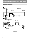
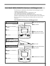
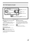
1 POWER switch
Setting the switch to ON (1 ) turns the power on.
The level meter will light.
Setting the switch to OFF (
o) turns the power off.
2 PHONES connector (stereo phone jack)
Connect 8-ohm stereo or monaural headphones.
Note that the output is monaural even when stereo
headphones are connected.
3 MONITOR volume control
Adjusts the volume of the headphones.
4 Level meter
Indicates the level of the audio signal output to the
LINE OUT !¡, TELEPHONE COUPLER !™ and
DELEGATE’S/CHAIRMAN’S UNIT !¢
connectors.
5 Volume controls
Used to adjust the level of the following sound.
D/C UNIT SP volume control: Adjusts the level
of the audio signal output to the chairman’s
unit/delegate’s unit.
D/C UNIT MIC volume control: Adjusts the
input level of the audio signal sent from the
microphones on the chairman’s units and
delegate’s units.
MIC/LINE 1 volume control: Adjusts the input
level of the signal input through the EXT IN-1
MIC or LINE connector.
MIC/LINE 2 volume control: Adjusts the input
level of the signal input through the EXT IN-2
MIC or LINE connector.
When the MIC/LINE switch of the EXT IN-1 or
EXT IN-2 connector is set to LINE, the input level
of the signal input through the LINE connector can
be adjusted.
When the MIC/LINE switch of the EXT IN-1 or
EXT IN-2 connector is set to MIC, the input level
of the signal input through the MIC connector can
be adjusted.
6 MIC (microphone mode) LIMIT ON/OFF
button
Selects the microphone mode for the delegate’s
units.
The microphone of the chairman’s unit remains
live regardless of the setting of this button.
MIC (microphone) LIMIT ON: Press this button
to set the microphone to the speaker’s number
limitation mode. The button indicator lights.
Setting this mode allows the microphones of up
to five delegate’s units to be live at the same
time.
MIC (microphone) LIMIT OFF: Press the button
again to set the microphone to the speaker’s
number unlimitation mode. The button
indicator goes out. Setting this mode allows the
microphones of all delegate’s units to be live at
the same time.
7 DIRECT ACCESS ON/OFF button
This button is effective only when the SXA-120
Expansion Board (not supplied) is installed and the
SX-8300/SX-S100 Microphone Control Panel is
connected to the control unit.
While the SX-8300 is not connected, this button
indicator lights, even though it is not operative.
The button indicator does not go out even if you
press this button.
8 SEAT ASSIGN START/END button
This button is effective only when the SXA-120
Expansion Board (not supplied) is installed and the
SX-8300/SX-S100 Microphone Control Panel is
connected to the control unit for performing seat
assignment.
While the SX-8300 Microphone Control Panel is
not connected, the button indicator does not light
even if you press the button.
For details of the functions and how to use the DIRECT
ACCESS ON/OFF and SEAT ASSIGN START/END
buttons, refer to the manuals supplied with the SXA-120
Expansion Board.
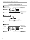
9 EXT UNIT IN/OUT (external unit input/
output) connectors (phone jack)
Connect to the howling suppressor unit or filter
unit (not supplied).
Notes
• Be sure to connect both the IN and OUT
connectors. Connecting only one of the two
connectors results in incorrect operation of the
unit.
• When it is not necessary to use the howling
suppressor or filter unit, disconnect cables from
both connectors.