


15
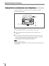
Connecting cord
(supplied with SX-T100)
to AC power source
AC power cord
(supplied with SX-M100)
Other party
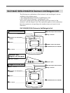
CONTROL UNIT
Cable with 20-pin
multi-connector
b)
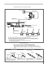
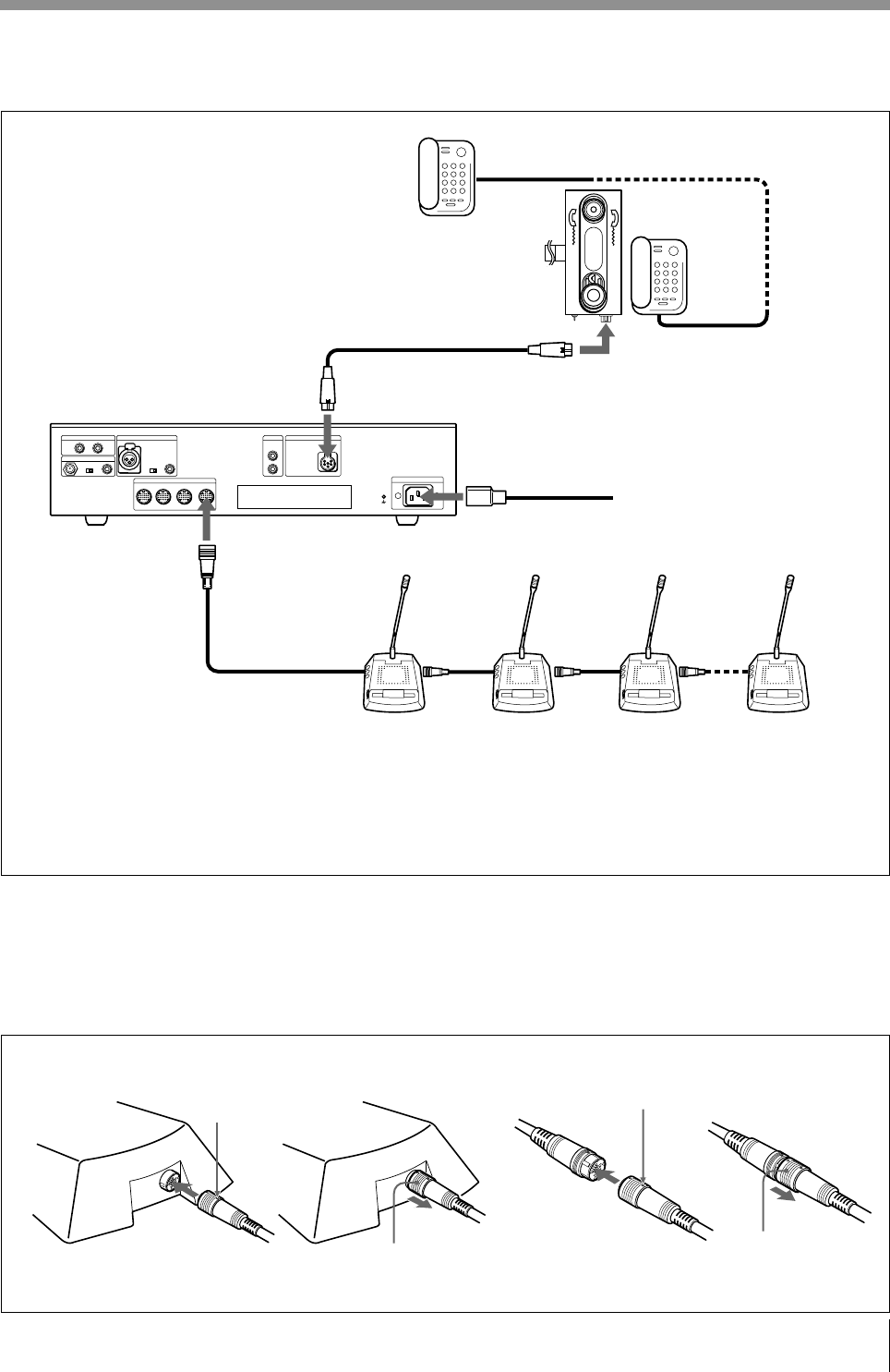
The figure below shows an connection example.
System connection example
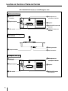
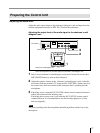
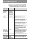
How to connect cables of the SX-C100A/SX-D100A
The figure below shows how to connect and disconnect the 20-pin multi-
connectors of the chairman’s/delegate’s unit and RK-1710/1713 connecting
cables.
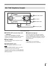
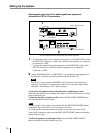
MIC LINE
EXT IN-2
EXT IN-1
LINE OUT
@TELEPHONE COUPLER
AC IN
1234
DELEGATE'S/CHAIRMAN'S UNIT
LINEMIC
LINE
MIC
LINE
1
2
IN
EXT UNIT
OUT
MIC
SX-T100
TELEPHONE COUPLER
AC IN
DELEGATE’S/CHAIRMAN’S UNIT
a)
SX-C100A
c)
SX-D100A
c)
(Up to 15 units of SX-C100A and
SX-D100A can be connected to one line.)
a) For details of connecting cables, see “How to connect cables” shown below.
b) You can extend the distance between units by using the RK-1710/1713 connecting cable (not supplied).
c) The desk-mounted SX-C150/SX-D150 can also be used in this system. Up to 15 desk-mounted SX-
C150 and SX-D150 units can be connected to one line.
The specially designed cables are used to connect these units to the system.
For details, contact your Sony dealer.
When disconnecting
White mark
White mark
When connecting
With the white mark on the 20-pin
multi-connector facing up, push the
connector home until it clicks.
When disconnecting
When connecting
Grasp the knurled part
of the connector and
pull it towards you.
Meet the white marks on each
connector and push the
connectors each other until they
click.
Grasp the knurled part of the
connector and pull it towards
you.
to output
connector
a)
Telephone line