


Chapter 2- Component Replacement
2-8
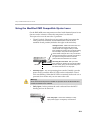
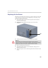
4 Using a star screw driver, disconnect the two wires connected to the
Terminal block (-48 VDC & RTN) of the failed DC PRM unit.
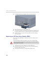
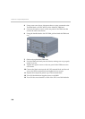
5 Unscrew the captive screws on the rear panel of the PRM unit that
secures the unit to the chassis.
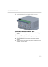
6 Using the handle fitted to the DC PRM, pull and slide the PRM unit
out.
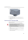
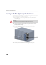
7 Slide in the replacement PRM unit.
8 Push the PRM unit firmly into the chassis, making sure it is properly
seated in its slot.
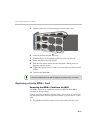
9 Tighten the captive screws on the rear panel of the PRM unit to the
rear chassis.
10 Connect the black wire into the -48 VDC terminal block and the red
wire to the RTN terminal block and tighten the two screws.
11 Replace the transparent plastic cap on the terminal block.
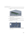
12 Turn ON the Main that supplies power to the RMX.
13 Turn ON the circuit breaker on each of the DC Power Rail Modules.