


Chapter 1- Hardware Description
1-26
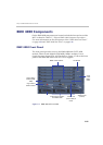
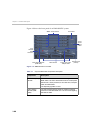
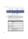
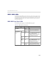
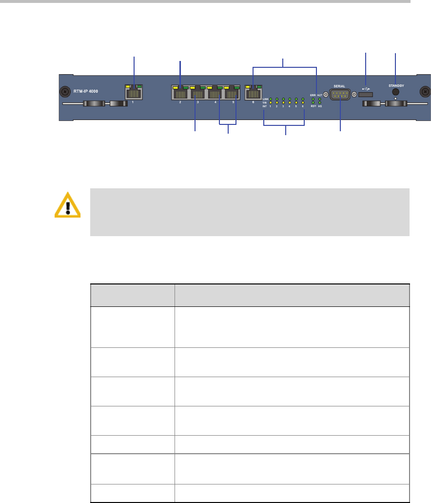
Figure 1-11 RMX 4000 RTM-IP 4000 Rear Panel Layout
The following items appear on the RMX 4000 rear panel:
LAN 6- 10/100Mb ShMG (Shelf
Manager) & LEDs
LAN 1- Modem
Connection
USB
Port
Standby button
& LED
LAN 2-
Management
Network
LAN 3 -
Signalling
network
Serial Port
LAN 4, 5 -
Empty
Internal LAN
connection
LEDs
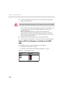
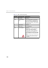
• LAN 4, LAN 5 and the Serial ports are only for debugging and not for
customer use.
• Do not remove the protective plastic caps from LAN 1, LAN 4 and LAN 5
ports.
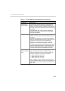
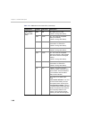
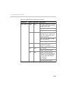
Table 1-8 RMX 4000 Rear Panel - RTM-IP 4000 Component Description
Item Description
LAN 1 Modem connection.
Note: LAN 1 is covered with a plastic cap that should not
be removed.
LAN 2 (CNTL
4000/CPU 1)
Management network/Web Client connection.
LAN 3 (CNTL
4000/CPU 1)
Signalling network, for Gatekeeper, Proxy or endpoint
connections.
LAN 4-5 (CNTL
4000/CPU 2)
Empty.
LAN 6 Shelf Manager connection.
Serial A 10/100 ShMG Shelf Manager connection.
For debugging purposes only.
USB USB key connection - TBD.