


Chapter 1- Hardware Description
1-28
ISDN/PSTN Clock Source
Each RTM ISDN card has its own primary and secondary clock source.
The first span to synchronize becomes the primary clock source and the
second span to synchronize becomes the secondary clock source. This
clock is used to synchronize ISDN spans only (it is not the system clock).
A single clock source triggers an alarm that can be turned off by setting
the appropriate flag in the system configuration.
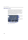
RTM LAN
The RTM LAN card routes data between the MPM+ cards and
components of the system, sends media by IP packets and provides
connectivity to external networks.
An RTM LAN card must connect directly to an MPM+ card. In an RMX
with a single MPM+ card, the RTM LAN card must be installed in the rear
panel slot on the
same level as the
MPM+
card.
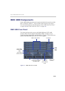
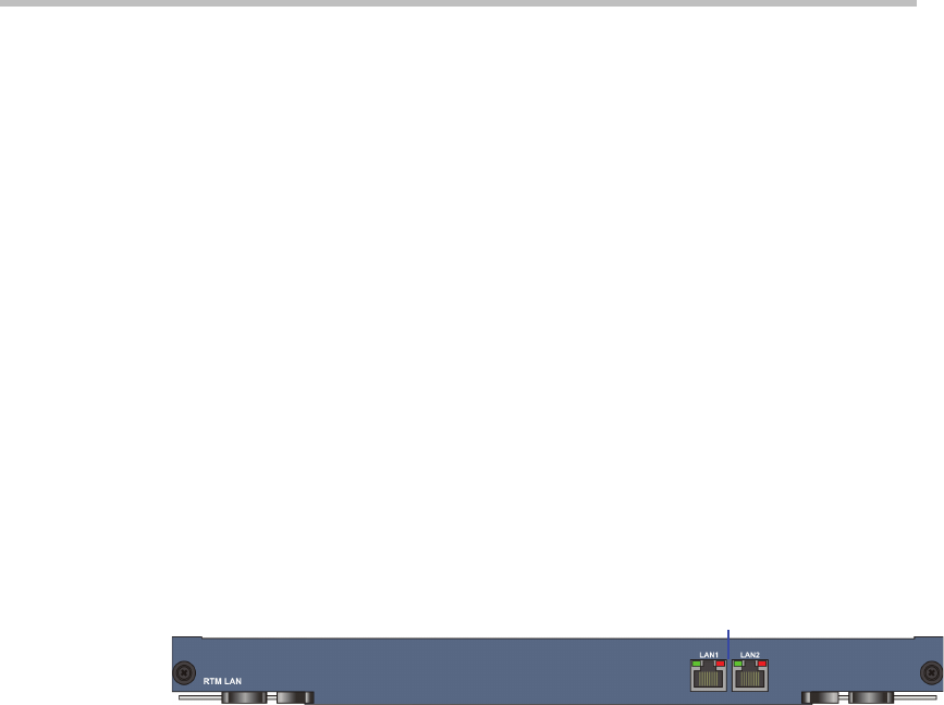
Each RTM LAN card includes 2 LAN ports and a maximum of four RTM
LAN cards can be installed on the RMX 4000.
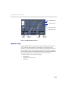
Figure 1-13RMX 4000 RTM LAN Rear Panel Layout
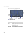
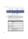
AC Power Entry Module (PEM)
An AC PEM includes a power inlet, EMI filter and backplane connectors.
Power input to the system is fed via a PEM (Power Entry Module)
through backplane into the power supply. Each AC power module has its
own dedicated power cable. The ON/OFF switch on the rear of the RMX
activates any power module installed on the RMX. An AC system has
three AC PEMs, one for each power module. On failure, both AC power
supplies and PEMs are hot swappable.
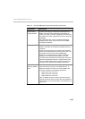
2 LAN Connections &
LEDs