


Polycom RMX 4000 Hardware Guide
1-23
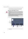
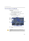
AC/DC Power
Supply Modules
The AC Power Supply drawers are located below the
MPM+ Cards and are connected to the backplane by
means of a power connector. Operating at 100-240 volts
AC 50/60 Hz all power supplies have built-in load sharing
capabilities.
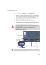
On systems with DC current, the Power Rail Module
(PRM) provides direct current to the rear of the RMX
through the backplane.
Fan Drawer Eight fans are mounted sideways and stacked in a
drawer. The drawer is connected to the Back-plane by a
connector.
Airflow is from right to left, and out the side of the MCU.
Each time a board temperature sensor passes one of its
thresholds an event is sent to the ShelfManager,
whereupon an threshold alert is posted on the RMX
Manager, and increases the fans speed. There are
currently 3 sets of thresholds: Normal, Major and Critical.
When the temperature reaches a critical threshold (and
the fan’s speed increase did not resolve the issue), the
controller of the relevant board initiates a shut down.
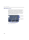
Multi Processor
Module+ (MPM+)
Card
The MPM+ cards, perform the various RTP, audio and
video processing functions on the RMX 4000 unit. TI
C6455 processors are at the core of each MPM+ card
which are available in the following assemblies:
• MPM+20 (20 CIF resources)
• MPM+40 (40 CIF resources)
• MPM+80 (80 CIF resources)
Note: An MPM+ located (on the front panel) must face
opposite (same slot level) an RTM LAN card (installed on
the rear panel). For more information, see
"RTM LAN” on
page 1-28.
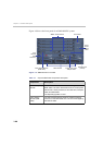
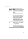
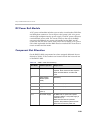
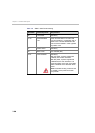
Table 1-7 Polycom RMX 4000 Component Description (Continued)
Component Description