


Polycom RMX 4000 Hardware Guide
1-29
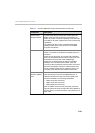
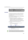
DC Power Rail Module
A DC power rail module includes a power inlet, circuit breaker, EMI filter
and backplane connectors. Power input to the system is fed via a power
rail through backplane into the power supply. Each DC power rail has its
own dedicated power cable. The circuit switch on the rear of the RMX
activates independently any power rail installed on the RMX. An DC
system has two DC rails, one for each power rail. On failure, a DC power
rail is field replaceable and the RMX must be switched OFF from the two
circuit switches and the mains.
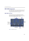
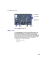
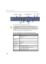
Component Slot Allocation
On the RMX™ 4000, components have been assigned dedicated slots as
defined in Table 1-9. Slot numbers are located on both the front and rear
of the RMX™ 4000.
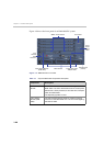
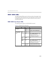
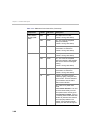
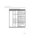
Table 1-9 RMX™ 4000 Slot Numbering
Slot ID/No. Card/Component Requirement
1-4 MPM+ Cards Mandatory: At least 1 MPM+ card is
required. Each media card also requires
either an RTM ISDN or an RTM LAN
card.
5 Fabric Switch
Module (FSM
4000)
Mandatory
6 CPU 2 Not Available (NA)
7 Logo Panel Not Available (NA)
8 CTNL 4000 unit
(CPU 1)
Mandatory
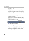
9-11 AC Power Supply An RMX with AC power has 3 power
supplies installed. A 3rd power supply is
redundant (n+1).
Note: Not used with DC powered
systems. DC powered systems receive
Direct Current from the power rail .