


SpectraLink 6100 MCU: Installation and Operation: SpectraLink 6000 System
PN: 1725-36097-001_J.doc
38
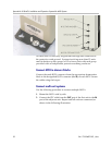
5. Once the Base Station is anchored to the fastener, lift the acoustical
tile and plug the RJ-45 8-pin modular plug into the connector on
the top of the Base Station.
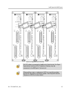
— The LED will blink red and green as the system software
downloads to the Base Station and the Base Station is tested.
— When the LED blinks amber, the system is ready for operation.
— When the LED blinks green, a telephone has established a
radio link with that Base Station.
— If the LED turns solid red, there should be an error message on
the MCU’s
STATUS LEDs. Refer to Chapter 8, section
Troubleshoot Error Codes.
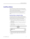
Mount Base Stations on finished ceilings
If your site does not have a dropped tile ceiling, the Base Station can
be mounted to a finished ceiling or wall with a 4 to 5” long 1/4” –20
TPI plastic or nylon screw or bolt (such as a lag screw).
The customer’s wire contractor is responsible for this installation.
1. Drill two holes approximately 1” apart. Make the holes large
enough to accommodate the RJ-45 connector and a bolt to secure
the Base Station.
2. Insert a wide washer above the ceiling, then screw the bolt into
the beam or ceiling.
3. Insert three nuts on the bolt, then screw the Base Station into the
bolt, being careful not to insert the bolt more than 1/3”, five full
turns, into the Base Station.
If the ceiling is open with I-beams or pipe construction, mount the
Base Station with I-beam clamps or pipe clamps.