


Install SpectraLink 6000 System
PN: 1725-36097-001_J.doc
31
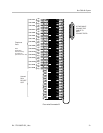
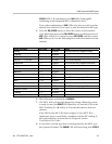
Install MCUs
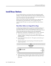
Mount MCUs to wall
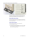
The MCUs are designed to be mounted on a backboard of 3/4”
plywood, securely fastened to the wall. Mount the MCUs vertically,
side by side, using 2.75” spacing center-to-center for each unit. Do not
stack MCUs on top of one another.
To mount the MCUs:
1. Using a 1/8” drill bit, drill four pilot holes, on 2” x 12.1” centers.
2. If installing only one MCU, insert the #8 x 3/4” screws in the pilot
holes and tighten, leaving a 1/8” to 1/4” gap from the wall.
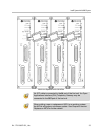
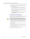
3. If installing more than one MCU, the ESD bonding strap(s) must
be installed between adjacent units:
4. Remove the screws from the bottom of adjacent units.
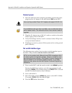
5. Place the ESD strap over the pilot holes that span two units, and
hold it against the plywood backboard.
6. Place the star washer on top of the ESD strap.
7. Insert the #8 x 3/4” screw and tighten to leave 1/8” to 1/4” gap
from the wall.
8. Repeat for all ESD straps.
9. Slide the MCU over the screws until it drops in place.
10. Tighten screws fully.
11. Ground the unit per Grounding instructions below.
Grounding instructions
Safety
Warning
The metal chassis of this unit may contain leakage currents (i.e.,
"touch" current) which is cumulative when multiple units are
connected together to form a system. To prevent the summation of
leakage currents from being present on exposed metal surfaces, the
following installation procedure must be followed.
All system units must be grounded to a protective earth by means of
the grounding stud located on the rear panel. Refer to the illustration
below for recommended continuity connection.