


Install SpectraLink 6000 System
PN: 1725-36097-001_J.doc
29
Check Components
The following items should be at the installation site.
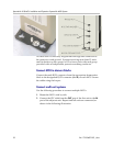
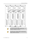
SpectraLink 6100 Master Control Unit Depending on the size of
your system, there may be up to four MCUs, which will be
chained together to extend the coverage area.
The SpectraLink 6000 System MUST contain only SpectraLink
6100 MCUs. Link 150 Model 2 MCUs or Model 1 MCUs cannot be
used in an M3 system.
AC Adapter Supplies power to the SpectraLink 6100 MCU.
Use only the provided Class II AC Adapter with output 24V DC, 1A.
IPC Cable Each MCU is shipped with one inter-processor
communication (IPC) cable to carry signals between SpectraLink
6100 MCU units. It is used only when multiple MCUs are chained
together.
Base Stations SpectraLink Part Number RCC 400/410 or RCO
400/410 (for outdoor use). Your system may have up to four Base
Stations for each MCU shipped.
Base Station Mounting Hardware A ceiling clip and plastic bolt
used to attach each Base Station to the T-bar ceiling tile grid.
MCU Mounting Hardware Four #8 x 3/4” panhead wood screws
and star washers, used to mount the MCU to the wall.
ESD Bonding Straps To provide static protection for the MCU.
SpectraLink 6000 Wireless Telephones The correct number of
handsets for this installation.
Battery Chargers SpectraLink 6000 Wireless Telephones require a
Battery Charging system, usually one per handset.
Battery Packs The system may have one or more spare Battery
Pack per handset, depending on the needs at your location.
Documentation and Training Information This includes a user guide
for each handset and the CD which contains all referenced
documents.