


SpectraLink 6100 MCU: Installation and Operation: SpectraLink 6000 System
PN: 1725-36097-001_J.doc
14
The Front Panel of the SpectraLink 6100 MCU
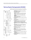
The MCU’s front panel contains the connections to the telephone
system, switches to control system administration, and status LEDs.
1. STEP button: Selects a specific line or Base Station
during registration process.
2. Mode switch: Selects the mode of operation for the
SpectraLink 6100 MCU.
ADMIN: Administration mode, used to set up system
features to match features on the telephone system.
NORMAL: Normal mode, used during day-to-day
operations.
REGISTER: Registration mode, used to add or delete
handsets and Base Stations.
3. DEL/ENTER button: Removes a registered handset from
the system.
4. IPC IN port: Used to connect preceding MCUs in a multi-
MCU configuration.
5. IPC OUT port: Used to connect sequential MCUs in a
multi-MCU configuration or to connect to an Open
Applications Interface (OAI) Telephony Gateway.
6. ERROR LED: Flashes when the system has detected an
error. When flashing, check the STATUS LEDs for an error
code.
7. STATUS LEDs: Indicate system error messages and
status. See SpectraLink 6100 MCU: Installation and
Operation for more information.
8. LINE LEDs: Indicate the line status of each handset:
ringing, in-use or not active.
9. BASE STN LEDs: Indicate the status of each Base
Station.
10. CONN A or B: RJ-21 connector to the cross-connect
demarc block. Connector B is supplied and used only
with four-wire digital interface.
11. PWR jack: Connects to the AC adapter to supply power
to the system.
CAUTION: Use only the provided Class II AC Adapter
with output 24V DC, 1A.
12. Grounding lug: For use on the analog interface MCU
(SCA-5XX).