


Install SpectraLink 6000 System
PN: 1725-36097-001_J.doc
35
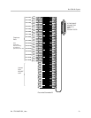
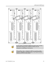
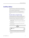
STATUS LEDs 1, 2, and 4 must be lit. LINE LEDs 1 through 8
(indicating an unconfigured MCU) should also be lit.
If any other combination of
LINE LEDs is lit, then a switch type has
already been selected. Go to step 5 to pick the desired switch type.
5. Press the
DEL/ENTER button to select the correct switch interface
type. With each press of the
DEL/ENTER button, a different series of
LINE LEDs will be lit. Continue to press DEL/ENTER until the correct
LINE LEDs are lit. Use the following list to select the desired switch
interface.
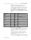
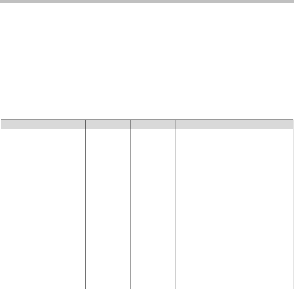
Switch Interface Line LEDs MCU Type Notes
Analog 1 SCA5xx The SCA will only support Analog.
Comdial 3 SCU5xx
DEFINITY – Two-wire 1, 4 SCU5xx
DEFINITY – Four-wire 1, 5 SCF5xx Four-wire Interface.
Executone 2, 5 SCB5xx The SCB will only support Executone.
Fujitsu 2, 4 SCU5xx
Inter-Tel 2, 3, 4 SCU5xx
Meridian 1, 2 SCU5xx
Merlin Legend 1, 3 SCF5xx Four-wire Interface.
Mitel 1, 2, 3 SCX5xx The SCX will only support Mitel.
NEC 1, 2, 4 SCU5xx
Norstar 2 SCU5xx
Panasonic 5 SCP5xx The SCX will only support Panasonic.
Siemens / Rolm 4 SCU5xx
Toshiba 2, 3 SCU5xx
Unconfigured 1 through 8
6. Move the mode switch back to NORMAL.
7. The MCU will cycle through diagnostic testing. When the system
is ready for use, the
ERROR LED should be off, and the LED for the
MCU Number (
1 to 4) will be lit. This should take less than two
minutes.
If the LED for the MCU ID does not light, or if an MCU ID is
duplicated, there is most likely a problem with the IPC cabling. If
the system displays an error refer to Chapter 8, section
Troubleshoot Error Codes.
8. If you select a switch type that is not supported by the MCU type,
the system will alarm. The
ERROR LED will flash along with STATUS