


SpectraLink 6100 MCU: Installation and Operation: SpectraLink 6000 System
PN: 1725-36097-001_J.doc
34
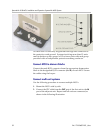
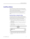
Connect power
1. Once the units have been properly grounded, connect the power
plug from the AC adapter to the jack labeled
PWR on the MCU.
Use only the provided Class II AC Adapter with output 24V DC, 1A.
For installations with more than one MCU, use an outlet strip with a
built-in power switch. This allows the MCUs to be turned on and off
together.
2. Plug the AC adapter into a 110V AC outlet or switch on the outlet
strip to apply power to the MCU.
3. Verify that leakage current ("touch" current) is below 250 μA rms
on exposed metal surfaces.
4. If leakage is excessive, power off the system and re-verify ground
path continuity.
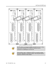
Set switch interface type
The following steps explain how to assign a switch interface type to
the MCU. This procedure must be done on each MCU.
MCUs can be enabled with different/mixed PBX integrations within
the same system and operate normally. However, the MCUs must
be running the same software. See Chapter 8 section Replace an
MCU for details on the software update procedure. If you need
additional help, please contact the Polycom Customer Support for
assistance.
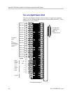
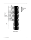
1. Power on the MCU with the mode switch in the
NORMAL position.
Because the MCU does not have a switch type assigned, it will
alarm (the
ERROR LED will flash along with STATUS LEDs 1, 2, 3, 4,
and
5). This should take less than 2 minutes.
2. Power off the MCU.
3. Move the mode switch to
ADMIN and power on the MCU. Within
15 seconds,
STATUS LEDs 2 and 4 will light.
4. Press the
STEP button three times.