


SpectraLink 6100 MCU: Installation and Operation: SpectraLink 6000 System
PN: 1725-36097-001_J.doc
20
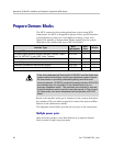
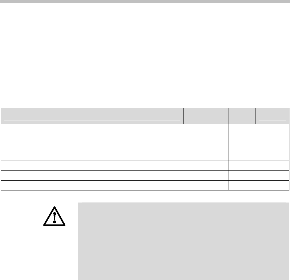
Prepare Demarc Blocks
The MCU connects to the existing telephone system using RJ-21
connections. An MCU is designed to operate with a specific interface
to the telephone system: two-wire digital or analog, or four-wire
digital. The number of demarcation blocks required for the system
depends on the number and type of MCUs installed.
Interface Type
MCU
Part Number
Wire
Pairs
# Blocks
Analog POTS SCA-5XX 1 1
Universal Digital Interface (Norstar, Meridian, Comdial, Fujitsu,
Inter-Tel, DEFINITY 2-wire, NEC, Rolm, Toshiba)
SCU-5XX 1 1
Merlin Legend and DEFINITY 4-wire SCF-5XX 2 2
Mitel (DNIC) SCX-5XX 1 1
Panasonic (Universal 2-wire Auxiliary Digital) SCP-5XX 1 1
Executone (Universal 4-wire Auxiliary Digital) SCB-5XX 2 2
If the wiring between the SpectraLink 6100 MCU and the telephone
system leaves the building, consult your telephone system manual
for instructions on providing adequate lightning and other over-
current protection. All MCUs (except the analog interface SCA-5XX)
are intended only for connection to the isolated side of an on-
premises telephone switch. The interfaces are intended to connect
to digital telephone switch ports that provide signals of 5Vp-p (max)
AC component, and some telephone switches provide a 48 V DC
offset.
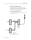
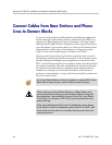
Based on the number and type of interfaces in the system, determine
the number of 25-pair cables required to connect line ports and Base
Stations to the demarcation blocks.
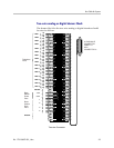
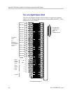
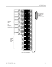
The diagrams which follow provide an overview of the connections.
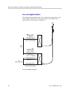
Multiple power pairs
Some sites may prefer to wire Base Stations to a separate demarc
block in order to split out power pairs.