


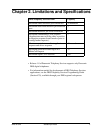


Section 520 - TSAPI Chapter 3. Installation
DBS-92-520 Issued April 2000 7
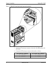
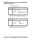
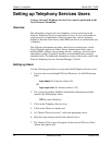
5. Connect the provided serial cable from Port 1 (or Port 2) to the serial port
on the Network Server. The cable must be configured as shown in Figure
2 below. The API port used must match the DBS API Port Type setting
specified in FF1 2# (41-42)# 1# (0-1)# and the port specified with the
NetWare Loadable Module
driver “Panadrvr”. See “Programming the
DBS” on page 8 and “DBS Driver Installation” on page 9 for more
information.
Note:
If the distance from the DBS to the server exceeds 50 feet, line
extenders or short range modems are required.
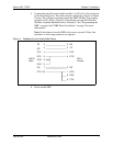
Figure 2. Telephony Services Serial Cable Pinout
6. Power on the DBS.
8
33
6
20
1
75
8
6
54
47
22
TD
DB-25
Male
DB-9
Female
RD
CTS
RTS
DSR
DCD
SG
DTR
RD
TD
RTS
DTR
SG
DCD
DSR
CTS