


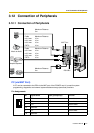

3.12 Connection of Peripherals
Installation Manual 217
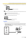
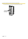
Connection Charts
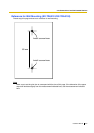
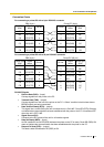
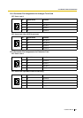
For connecting a printer/PC with a 9-pin RS-232C connector
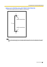
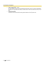
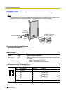
For connecting a printer/PC with a 25-pin RS-232C connector
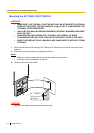
RS-232C Signals
• Receive Data (RXD):…(input)
Conveys signals from the printer or the PC.
• Transmit Data (TXD):…(output)
Conveys signals from the unit to the printer or the PC. A "Mark" condition is held unless data or
BREAK signals are being transmitted.
• Data Terminal Ready (DTR):…(output)
This signal line is turned ON by the unit to indicate that it is ON LINE. Circuit ER (DTR) ON does
not indicate that communication has been established with the printer or the PC. It is switched OFF
when the unit is OFF LINE.
• Signal Ground (SG)
Connects to the DC ground of the unit for all interface signals.
• Data Set Ready (DSR):…(input)
An ON condition of circuit DR (DSR) indicates the printer or the PC is ready. Circuit DR (DSR) ON
does not indicate that communication has been established with the printer or the PC.
• Request To Send (RTS):…(output)
This lead is held ON whenever DR (DSR) is ON.
Printer/PC (9-pin)
Circuit Type
(EIA)
BB
BA
CD
AB
CC
CA
CB
Signal
Name
RD (RXD)
SD (TXD)
ER (DTR)
SG
DR (DSR)
RS (RTS)
CS (CTS)
Pin No.
2
3
4
5
6
7
8
PBX (9-pin)
Signal
Name
Pin No.
RD (RXD) 2
SD (TXD) 3
ER (DTR) 4
SG 5
DR (DSR) 6
RS (RTS) 7
CS (CTS) 8
Circuit Type
(EIA)
BB
BA
CD
AB
CC
CA
CB
Printer/PC (25-pin)
Signal
Name
Circuit Type
(EIA)
1FG AA
3 RD (RXD) BB
2 SD (TXD) BA
20
ER (DTR) CD
7SG AB
5 CS (CTS) CB
6 DR (DSR) CC
CF4 RS (RTS)
Pin No.
PBX (9-pin)
Circuit Type
(EIA)
Signal
Name
Pin No.
BB RD (RXD) 2
BA SD (TXD) 3
CD ER (DTR) 4
AB
SG 5
CC DR (DSR) 6
CA RS (RTS) 7
CB CS (CTS) 8