


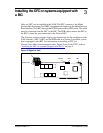
20 Installing the DFC on systems equipped with a BIC
FAX Installation Guide P0886634 Issue 1.0
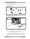
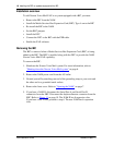
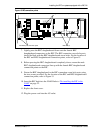
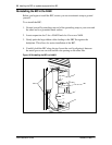
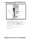
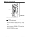
2. Place the BIC on a flat surface, with the components facing up. Refer to
Figure 15
on page 21.
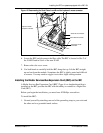
3. Unpack the small plastic bag from the shipping container. Make sure you have
two screws and two jumpers.
4. Locate JP1 and JP2 on the BEC. JP1 and JP2 are located next to the PEB
connector.
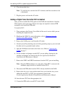
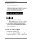
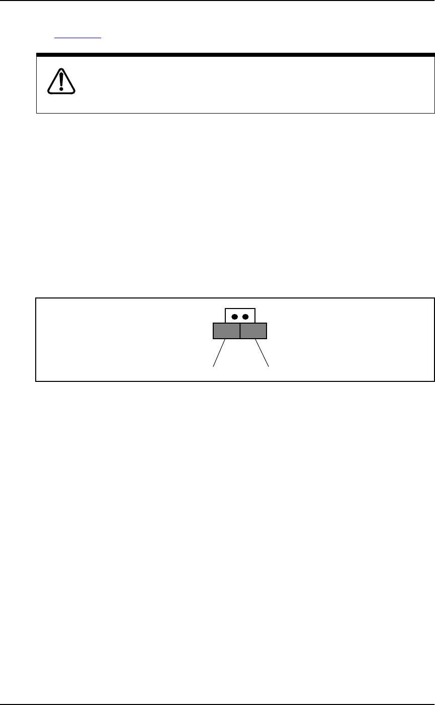
5. Remove the two jumpers from the small plastic bag. Install the two jumpers in
an “open” position on the bottom pin of JP1 and JP2. For the jumper to be in
the “open” position, the outside half of each jumper must not cover a pin.
Refer to Figure 14 for the jumper positions.
Figure 14 BEC jumper position
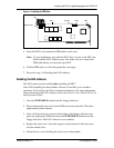
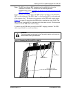
6. Unpack the BEC daughterboard from the shipping container and antistatic
bag. The BIC is equipped with two posts at the bottom of the board for
connection of the BEC daughterboard. Handle the BEC daughterboard by its
edges at all times. Do not touch any card components. Make sure you have the
two screws that came with the BEC daughterboard.
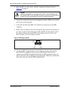
Caution
Failure to place the BIC on a flat surface may result in serious damage to the
BIC. While the BIC is out of the NAM, be careful not to slide or catch the back of
the BIC, this may cause damage to the pins on the back of the board.
Jumper Jumper
JP1
JP2