


10
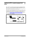
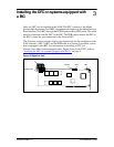
Installing the DFC on systems equipped with DVCs
FAX Installation Guide P0886634 Issue 1.0
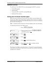
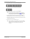
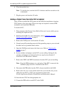
3. Switch SW1 should be set according to the following table:
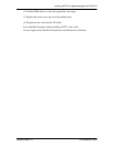
4. Switch SW2 should be set according to the following table:
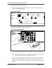
5. Ensure there is a jumper on position 10 of the INTERRUPT.
Note: The settings in these table are the default values and should be set
properly when the board is received. Refer to Figure 2
on page 5 for
the location of the switch SW1, SW2 and the INTERRUPT jumpers.
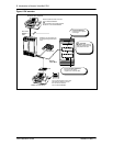
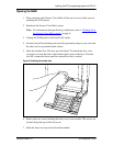
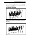
6. Carefully hold the DFC along the top only. Insert the card by aligning
between the metal groove on one side and the slot opening on the other side.
7. Push the DFC straight in until it is snugly in place. Ensure the edge connector
is firmly inserted into the socket.
8. Fasten the slot cover screw in the DFC slot cover.
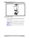
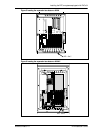
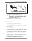
Note: If there is a DVC in slot 6 of the NAM, you must connect the PEB
cable to the DFC before installation. If there is a DVC in slot 7 of the
NAM II, you must connect the PEB cable to the DFC before
installation.
Position 87654321
State off on off off on on on on
Position 2 1
State on on