8
If you plan to mount the control unit and modem
separately, follow these steps to detach the
control unit from the modem, attach the strain-
relief brackets, and attach the “L” mounting
brackets.
a. Remove the 12 #6-32 screws and washers
securing the rack-mount brackets to the front
of the control unit and modem (see Figure 9
on page 7). Remove the brackets.
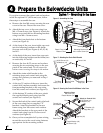
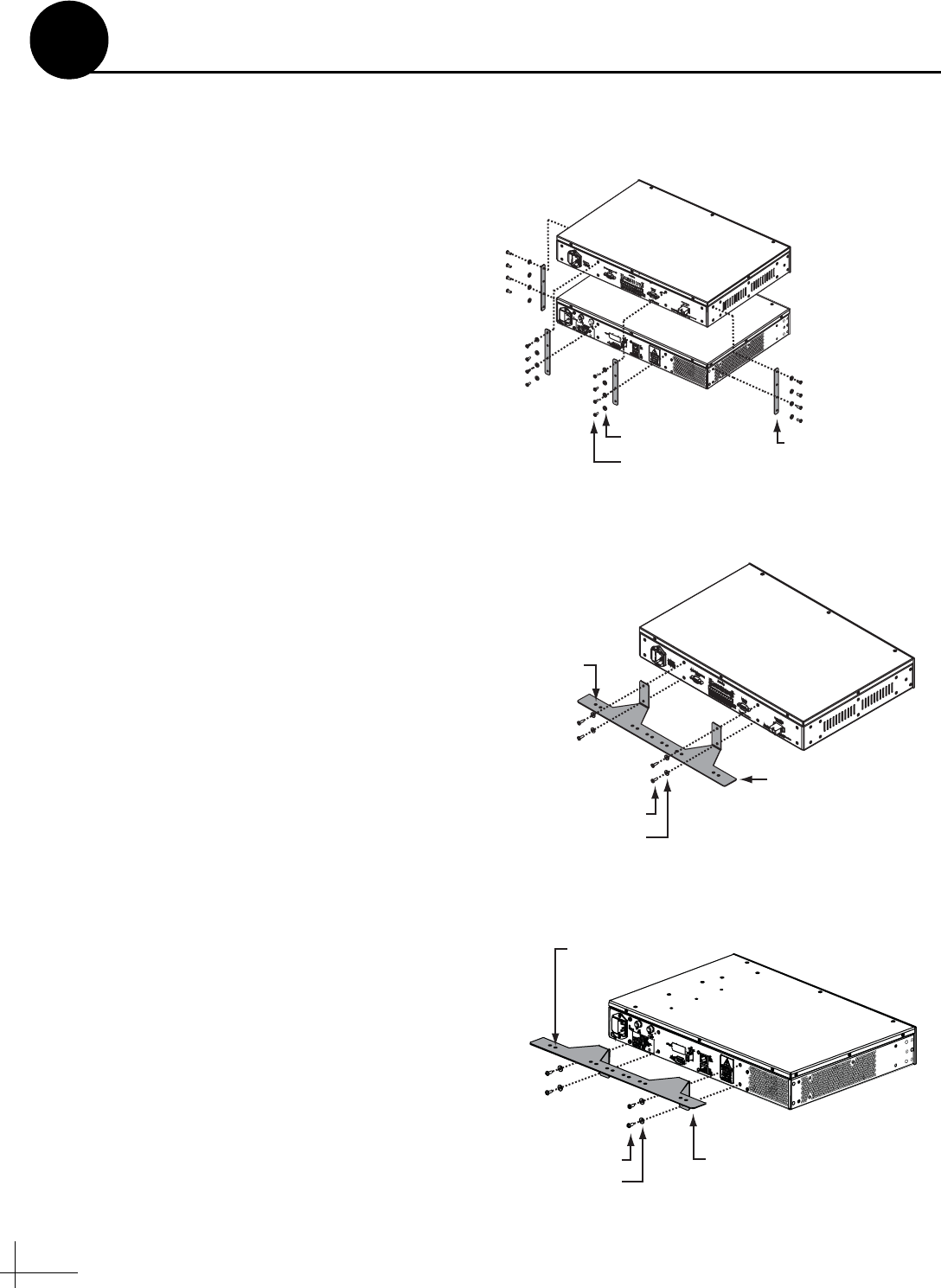
b. Remove the 16 #6-32 screws and washers
securing the four metal retaining straps to the
control unit and modem (see Figure 12).
Remove the straps.
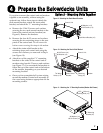
c. Attach a strain-relief bracket to the back of
the control unit using four of the screws and
washers you removed in Step b (see
Figure 13).
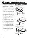
d. Attach a second strain-relief bracket to the
back of the modem using four of the screws
and washers you removed in Step b (see
Figure 14).
e. Attach two of the supplied “L” brackets to
the sides of the control unit using four #6-32
screws and washers (see Figure 11 on page 7).
You can attach the brackets at either the top
or bottom of the control unit, depending on
your desired mounting location.
f. Attach the two other supplied “L” brackets to
the sides of the modem using four #6-32
screws and washers (see Figure 11 on page 7).
You can attach the brackets at either the top
or bottom of the modem, depending on your
desired mounting location.
g. Once you have completed all system wiring,
mount the control unit and modem to the
vessel using fasteners appropriate for the
mounting surface.
#6-32 Screw (x16)
#6 Washer (x16)
Strap (x4)
Modem
Control Unit
Figure 12: Detaching the Retaining Straps
#6 Washer (x4)
#6-32 Screw (x4)
Strain-Relief
Bracket
Tie-wrap
Holes (x12)
Control Unit
Figure 13: Attaching the Bracket to the Control Unit
#6 Washer (x4)
#6-32 Screw (x4)
Strain-Relief
Bracket
Tie-wrap
Holes (x12)
Modem
Figure 14: Attaching the Bracket to the Modem
Prepare the Belowdecks Units
4
Option 3 - Mounting Units Separately


