


5
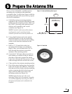
Before you begin, consider the following
installation guidelines for the belowdecks units.
Control Unit and Modem
• Select a mounting location in a dry, well-
ventilated area belowdecks away from any
heat sources or salt spray.
• Be sure the front panels will be easily
accessible to the user.
• Leave enough room at the rear panel for
connecting the cables.
• You have several options for mounting the
control unit and modem:
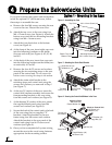
Option 1 - Inside the optional case
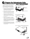
Option 2 - To a horizontal surface together
using two L-brackets
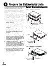
Option 3 - To a horizontal surface
separately using four L-brackets
NOTE: The control unit and modem are sized to
fit a standard 19" (482.6 mm) equipment rack.
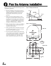
• To use the supplied data and power cables,
the control unit must be located within 100 ft
(30 m) of the antenna. However, you can
order 150 ft (45 m) cables if a longer cable run
is necessary (see Figure 20 on page 11).
Router and MTA
• To use the supplied Ethernet cables, select a
mounting location within 25 ft (7.5 m) of the
modem (maximum length = 200 ft (60 m)).
• Be sure the location provides adequate WiFi
reception. Do not install the router in an area
surrounded by metal or near any electrical
devices that generate RF noise.
Remote Service & Support Module
• To use the supplied serial data cable, select a
mounting location within 25 ft (7.5 m) of the
control unit (maximum length = 50 ft (15 m)).
• Be sure the location provides adequate GPRS
cellular reception.
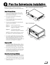
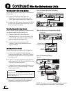
11.31"
(28.7 cm)
2.61"
(6.6 cm)
16.75"
(42.5 cm)
Figure 4: Control Unit or Modem Dimensions (Identical)
20.5"
(52.1 cm)
11.3"
(28.7 cm)
20.5"
(52.1 cm)
Figure 5: Case Dimensions
Plan the Belowdecks Installation
3