20
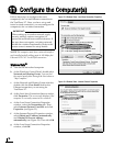
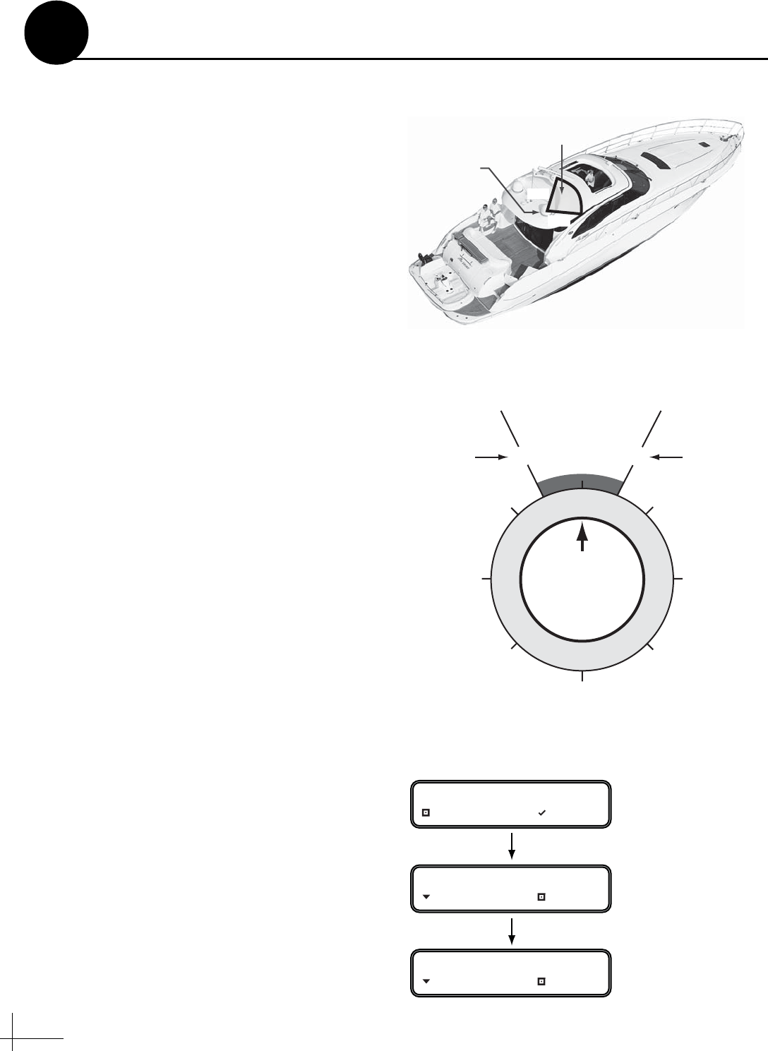
To prevent exposure to RF energy, which may be
harmful to people who stand within 36 feet
(11 meters) of the antenna, you can configure up
to two RF radiation hazard zones for areas where
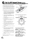
crew and/or passengers frequent (see Figure 41).
The system will disable the transmitter whenever
the antenna is pointing within one of these zones.
Follow these steps to set up an RF hazard zone.
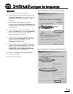
a. Determine the necessary azimuth range for
the RF hazard zone(s). You will need to enter,
in clockwise order, beginning and ending
azimuths (>4° apart) relative to the antenna’s
forward arrow, which should be pointing
toward the bow (see Figure 42).
b. At the control unit, press MENUS until the
display shows “CONFIGURATION.” Then
press ACCEPT.
c. Press MENUS until the display shows “SET
HAZARD ZONE.”
d. Press CHANGE until the display shows “SET
HAZARD ZONE = YES.” Then press
ACCEPT.
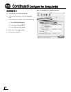
e. At “ZONE 1,” press CHANGE. A cursor
appears under the first number in the
azimuth range for RF hazard zone #1.
f. Press CHANGE until the number is set to the
first digit of the beginning azimuth for the
first hazard zone.
g. Press ACCEPT. The cursor moves to the next
number.
h. Repeat steps f and g to set the remaining
digits of the desired RF radiation hazard
zone. Then press ACCEPT.
i. At “Zone 2,” repeat steps e-h to set the range
for the second RF hazard zone, if desired.
j. At “XMT IN ZONES,” verify that the display
shows “XMT IN ZONES = NO.” Then press
MENUS.
k. Press EXIT to exit the menu.
NOTE: For more details, refer to the Configuration
section of the User’s Guide.
335
025
Antenna
RF Radiation
Hazard Zone
Figure 41: Example of an RF Radiation Hazard Zone
Antenna
000
180
090270
045
135
225
315
Forward
335 025
RF Radiation
Hazard Zone
(Example)
Beginning
Azimuth
Ending
Azimuth
Figure 42: Azimuths Relative to Antenna’s Forward Arrow
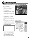
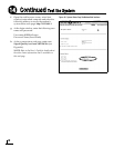
ZONE 1= 335-025
CHANGE ACCEPT
Step 1:
Set Zone 1
Azimuth Range
ZONE 2= 000-000
NEXT ITEM CHANGE
Step 2:
Set Zone 2
Azimuth Range
XMT IN ZONES= NO
NEXT ITEM CHANGE
Step 3:
Set to “NO”
Figure 43: Setup Process for RF Hazard Zones
Set Up RF Hazard Zones (Optional)
13


