


Intel Desktop Board DX48BT2 Product Guide
viii
25. Connecting the IDE Cable ..............................................................................46
26. Connecting a Serial ATA Cable........................................................................47
27. Internal Headers and Connectors....................................................................48
28. Back Panel Audio Connectors .........................................................................53
29. Location of the Chassis Fan Headers................................................................54
30. Connecting Power Supply Cables ....................................................................55
31. Location of the BIOS Configuration Jumper Block ..............................................56
32. Removing the Battery ...................................................................................62
33. Desktop Board DX48BT2 China RoHS Material Self Declaration Table ...................81
Tables
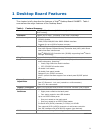
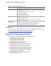
1. Feature Summary.......................................................................................... 9
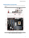
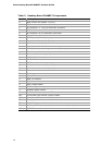
2. Desktop Board DX48BT2 Components .............................................................12
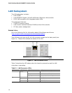
3. LAN Connector LEDs .....................................................................................16
4. Front Panel Audio Header Signal Names...........................................................49
5. HD Audio Link Header Signal Names ...............................................................49
6. Front Panel CIR Receiver (Input) Header Signal Names......................................50
7. Back Panel CIR Header Emitter (Output) Header Signal Names ...........................50
8. Chassis Intrusion Header Signal Names ...........................................................50
9. IEEE 1394a Header Signal Names ...................................................................51
10. USB 2.0 Header Signal Names........................................................................51
11. Front Panel Header Signal Names ...................................................................52
12. Alternate Front Panel Power LED Header Signal Names ......................................52
13. S/PDIF Connector Signal Names .....................................................................52
14. Jumper Settings for the BIOS Setup Program Modes..........................................57
15. Beep Codes .................................................................................................71
16. BIOS Error Messages ....................................................................................71
17. Safety Standards..........................................................................................73
18. Lead-Free Second
Level Interconnect Marks .....................................................79
19. China RoHS Environmentally Friendly Use Period Mark.......................................80
20. EMC Regulations...........................................................................................82
21. Product Certification Markings ........................................................................84