


Intel Desktop Board DX48BT2 Product Guide
52
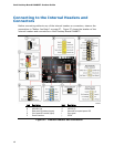
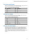
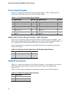
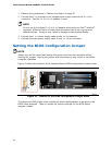
Front Panel Header
Figure 27, I shows the location of the front panel header. Table 11 shows the pin
assignments and signal names for the front panel header.
Table 11. Front Panel Header Signal Names
Pin Description In/Out
Pin Description In/Out
Hard Drive Activity LED Power LED
1 Hard disk LED pull-up to +5 V
Out 2 Front panel green LED Out
3 Hard disk active LED Out 4 Front panel yellow LED Out
Reset Switch On/Off Switch
5 Ground 6 Power switch In
7 Reset switch In 8 Ground
Power Not Connected
9 Power Out 10 No pin
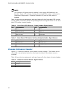
Alternate Front Panel Power LED Header
Figure 27, H shows the location of the alternate front panel power LED header. Pins 1
and 3 of this header duplicate the signals on pins 2 and 4 of the front panel header. If
your chassis has a three-pin power LED cable, connect it to this header.
Table 12 shows the pin assignments and
signal names for
the alternate front panel
power LED header.
Table 12. Alternate Front Panel Power LED Header Signal Names
Pin Description In/Out
1 Front panel green LED Out
2 No pin
3 Front panel yellow LED Out
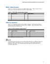
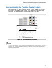
S/PDIF Connector
Figure 27, J shows the location of the S/PDIF connector. This connector can be used
with HDMI video cards that do not work with the HD Audio Link header (see
Figure 27, B).
Table 13 shows the pin assignments and signal names for
the S/PDI
F connector.
Table 13. S/PDIF Connector Signal Names
Pin Description
1 Vcc
2 S/PDIF Out
3 Ground