


Intel Desktop Board DX48BT2 Product Guide
50
NOTE
The Consumer IR option must be enabled in the system BIOS before it can
function. Press <F2> at boot to enter the system BIOS, and go to Advanced >
Peripheral Configuration > Enhanced Consumer IR, and set this option to
Enabled.
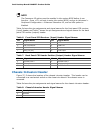
Table 6 shows the pin assignments and
signal names for
the front panel CIR receiver
(input) header and Table 7 shows the pin assignments and signal names for the ba
ck
panel CIR emitter (output) header.
Table 6. Front Panel CIR Receiver (Input) Header Signal Names
Pin Signal Name Pin Signal Name
1 Ground 2 LED
3 No Connection 4 Learn-In
5 +5 V Standby 6 Vcc
7 Key (no pin) 8 CIR Input
Table 7. Back Panel CIR Header Emitter (Output) Header Signal Names
Pin Signal Name Pin Signal Name
1 Emitter Out 1 2 Emitter Out 2
3 Ground 4 Key (no pin)
5 Jack Detect 1 6 Jack Detect 2
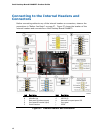
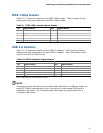
Chassis Intrusion Header
Figure 27, E shows the location of the chassis intrusion header. This header can be
connected to a mechanical switch on the chassis to detect if the chassis cover is
removed.
Table 8 shows the pin assignments and
signal names for
the chassis intrusion header.
Table 8. Chassis Intrusion Header Signal Names
Pin Description
1 Intruder
2 Ground