


Installing and Replacing Desktop Board Components
51
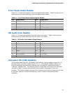
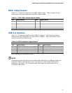
IEEE 1394a Header
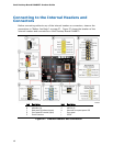
Figure 27, F shows the location of the IEEE 1394a header. Table 9 shows the pin
assignments and signal names for the IEEE 1394a header.
Table 9. IEEE 1394a Header Signal Names
Pin Signal Name Pin Signal Name
1 TPA1+ 2 TPA1-
3 Ground 4 Ground
5 TPA2+ 6 TPA2-
7 +12 V 8 +12 V
9 Key (no pin) 10 Ground
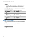
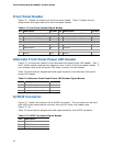
USB 2.0 Headers
Figure 27, G shows the location of the USB 2.0 headers. Table 10 shows the pin
assignments and signal names for each USB 2.0 header. Each USB header can be
used to connect two USB devices.
Table 10. USB 2.0 Header Signal Names
USB Port A USB Port B
Pin Signal Name Pin Signal Name
1 Power (+5 V) 2 Power (+5 V)
3 D- 4 D-
5 D+ 6 D+
7 Ground 8 Ground
9 Key 10 No Connection
Note: USB ports may be assigned as needed.
NOTE
Computer systems that have an unshielded cable attached to a USB port might not
meet FCC Class B requirements, even if no device or a low-speed USB device is
attached to the cable. Use a shielded cable that meets the requirements for a
full-speed USB device.