


Installing and Replacing Desktop Board Components
49
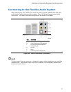
Front Panel Audio Header
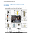
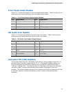
Figure 27, A shows the location of the front panel audio header. Table 4 shows the pin
assignments and signal names for the front panel audio header.
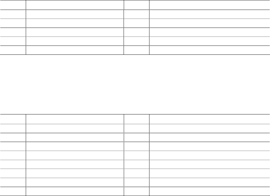
Table 4. Front Panel Audio Header Signal Names
Pin Signal Name Pin Signal Name
1 PORT 1L 2 GND
3 PORT 1R 4 PRESENCE#
5 PORT 2R 6 SENSE1_RETURN
7 SENSE_SEND 8 KEY (no pin)
9 PORT 2L 10 SENSE2_RETURN
HD Audio Link Header
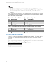
Figure 27, B shows the location of the HD Audio Link header. Table 5 shows the pin
assignments and signal names for the HD Audio Link header.
Table 5. HD Audio Link Header Signal Names
Pin Signal Name Pin Signal Name
1 BCLK 2 Ground
3 RST# 4 3.3 Vcc
5 SYNC 6 Ground
7 SDO 8 3.3 Vcc
9 SDI0 10 +12 V
11 SDI1 12 Key
13 No Connection 14 3.3 V STBY
15 No Connection 16 Ground
Consumer IR (CIR) Headers
The Desktop Board has two CIR headers: the input or receiver header (Figure 27, D)
and the output or emitter header (Figure 27, C). The receiver header consists of a
filtered t
ranslated infrared input compliant with Microsoft CIR specifications and a
“learning” infrared input. The learning input is a high-pass input which the computer
can use to “learn” to speak the infrared communication language of other user
remotes. The emitter header consists of two output ports which the computer can use
to emulate “learned” infrared commands in order to control external electronic
hardware.