


3.6.3. Worked Example: Doped Silica Waveguide Mode
In simulating waveguide devices, the first requirement is to have a source that produces a
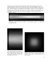
pure waveguide mode. Sometimes a Gaussian beam is sufficient, but often it is not,
especially when small reflections or phase shifts are important. Analytical solutions are
not often available for the modes of real dielectric guides, so a numerical procedure is of
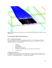
more general use. A good one is to illuminate a long section of model waveguide with
some approximate mode, and let the leaky components lose themselves. In this example,
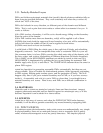
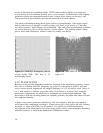
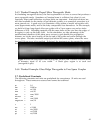
we build a 60-µm long doped silica core guide with a 5-µm square core and an index
difference of 0.02. Absorbing material with the same index as the core lines the edges of
th region, to suck up the leaky field. In this simulation, we take advantage of the
unidirectional character of the plane wave sources to gain double the propagation
distance: we let the wave bounce off the far end of the guide and return through the
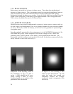
source plane. We take a modefile output just behind the source plane, where the wave
has had 110 µm or so to be purified. If desired, the treatment can be repeated by running
this source through the region again.
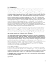
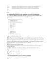
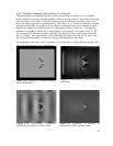
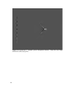
Figure 2.15: 60-µm long doped silica waveguide, excited with a circular Gaussian beam
of diameter equal to its core width. A black glass region is at each end
(waveguide1c.par).
3.6.4. Worked Example: Glass Ridge Waveguide to Free Space Coupler
3.7. Predefined Constants
The following constants and units are predefined for convenience. SI units are used
throughout. These names are reserved and cannot be redefined.
m = 1.0
km = 1000*m
cm = m/100
mm = cm/10
um = mm/1000
micron = um
nm = um/1000
angstrom = nm/10
s = 1
ms = s/1000
us = ms/1000
ns = us/1000
ps = ns/1000
41