


FLUX name=PwrIn xlo=0 xmax=10*um ylo=0 ymax=12*um z=zSource+1*um,
zinside = zSource+2*um xinside = xsize/2 yinside=ysize/2
FLUX name=PwrIn xlo=0 xmax=10*um ylo=0 ymax=12*um z=zOutput,
zinside = zSource+2*um xinside = xsize/2 yinside=ysize/2
END
OPTIMIZE
PENALTY (PwrIn-PwrOut)/PwrIn
...
END
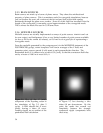
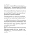
b. Mode matching between a device output and a Gaussian beam focused at
(X, Y, Z) = (5, 5, 20) µm, propagating along the +Z direction, with the integral being
carried out from 0 to 10 um in X and Y, in the plane Z=3 µm.
POSTPROCESS
...
MODEMATCH name=GaussianWaistUp ,
xinside= xsize/2,
yinside=ysize/2,
zinside=zsize/2,
function=CircularGaussian,
exi=1 exq=0,
eyi=0 eyq=0,
ezi=0 ezq=0,
xlo=0,
xhi=10*um,
ylo=0,
yhi=10*um
zlo=3*um,
zhi=3*um,
xfocus=5*um,
yfocus=5*um,
zfocus=20*um,
NA= 0.35,
direction=up,
file=somerandomfile.dat
c. Phase uniformity across a plane
There are several ways to do this. If you want the beam to go in a particular direction,
you can compute the mode match with a very low NA uniform beam; or if you want the
wavefront to be planar but don’t care exactly which direction it’s going, you can compute
integrals of the phase in small regions and compute the deviation from the best straight
line between them. This is more messy than it is difficult.
d. RMS Voltage across terminal points
If the terminals are separated in X, this could be (assuming they’re much less than a
wavelength apart):
INTEGRAL name=Vreal variable=Ex phase=0 xlo xhi ylo yhi zlo zhi
INTEGRAL name=Vimag variable=Ex phase=pi/2 xlo xhi ylo yhi zlo zhi
MERIT sqrt(Vreal*Vreal+Vimag*Vimag)
e. Power dissipation in a load
dissipation
f. Reflection from an interface
FLUX behind plane source/(FLUX in front+FLUX behind)
38