


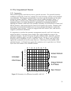
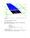
3.6.2. Worked Example: Optimizing a V Antenna
Thermodynamics dictates that the total power an antenna can deliver to its terminals
when excited by isotropic thermal radiation cannot be larger than kT per hertz (otherwise
you could put a hot resistor at the feed point, point the antenna at a colder object, and
have the resistor get hotter spontaneously). Thus there is a 1:1 trade-off between antenna
gain and solid angle: the product of the effective intercepted area of an antenna and the
equivalent width of its angular pattern in steradians cannot exceed λ
2
/2. The angular
pattern of an ordinary dipole has a solid angle of π steradians, so its gain is only 2. We
can do better, for narrower angular patterns, by raking the ends of the dipole forwards
into a V shape. This optimization run is adjusting the width and rake of the arms, and
the feed point impedance, to maximize the power dissipated in the load.
The parameters file used in this simulation is in Appendix A, along with the simplex file,
showing the progress of the optimization.
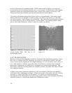
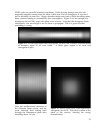
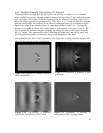
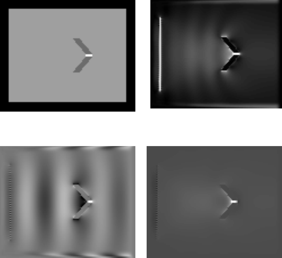
Figure 2.10 Optimized V antenna: refractive
index distribution
Figure 2.11 Optimized V antenna: E field
amplitude
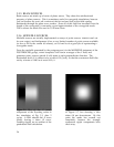
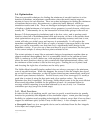
Figure 2.12 Optimized V-antenna:
Quadrature component of the E field
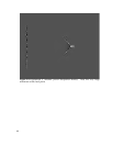
Figure 2.13 Optimized V antenna: Z
component of the Poynting vector
39