


STAR H GATE™
3
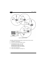
If connecting up to 16 STARGATE™ base stations in the same system, it is
necessary to use a custom cable having two different pinouts depending on the
network configuration.
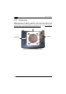
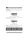
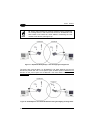
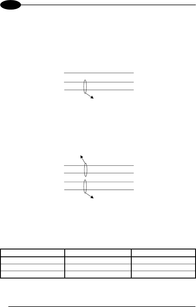
If each STARGATE™ present in the system is individually powered, the custom
cable pinout is the following:
5
2
RJ45
5
2
RJ45
1 1
VDC-
RS485-
RS485+
Twisted pair - RS-485 bus
Figure 10 - Powering Each STARGATE™ Individually
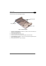
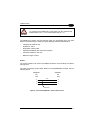
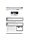
If the power is propagated from one base station to another by means of a single
power supply, the custom cable pinout is the following:
8
5
2
RJ45
8
5
2
RJ45
1 1
Twisted pair - RS-485 bus
Twisted pair - Power supply
VDC+
VDC-
RS485-
RS485+
Figure 11 - System with Power Propagation
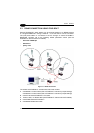
The power supply should be positioned in the middle of the network for a better
functioning.
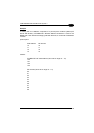
The total number of devices which can be connected to a single power supply
depends on the power supply voltage as shown in the following table:
Supply Voltage Consumption Max. Number of Devices
12 V 232 mA 4
24 V 344 mA 8
30 V 390 mA 10
Note: The values refer to a system adopting a cable 50 m long to connect the base
stations together.
12