


CONNECTIONS
3
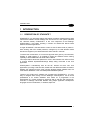
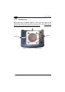
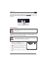
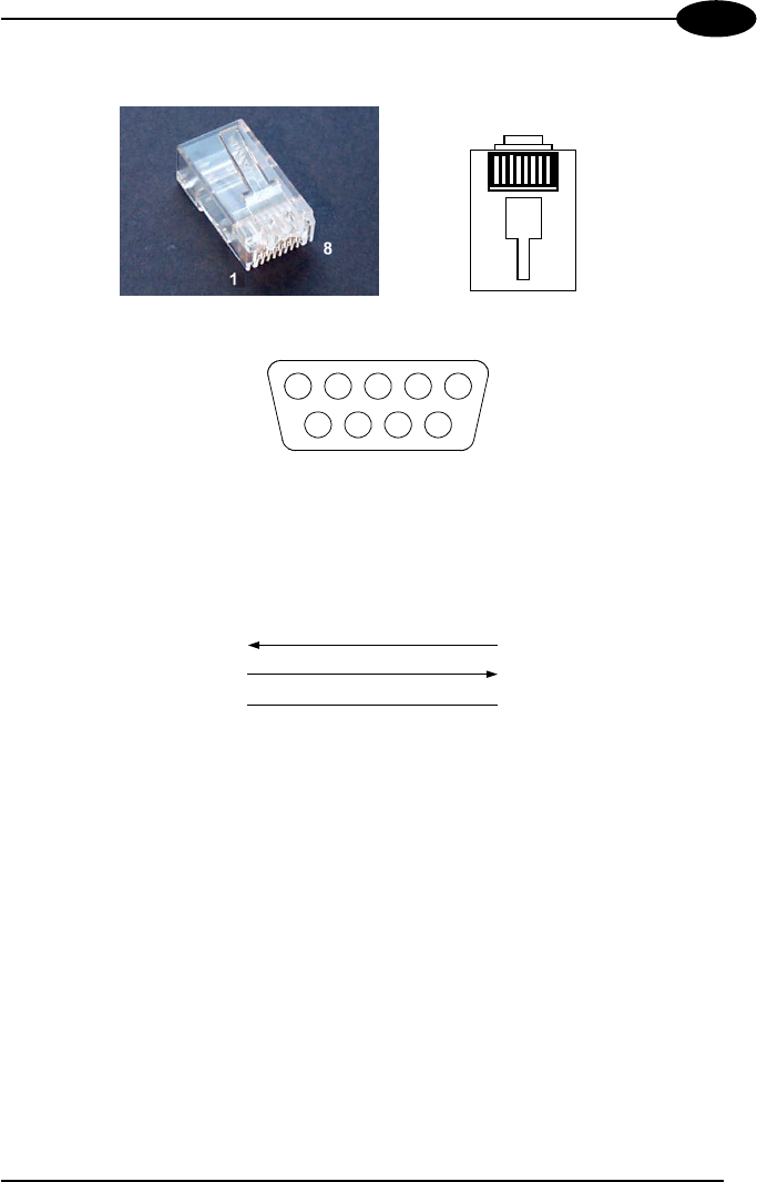
Pinout
8
1
Figure 5 - RJ45 Modular Connector
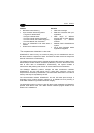
9
87
6
543
21
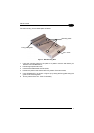
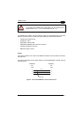
Figure 6 - 9-pin Female Connector
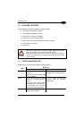
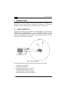
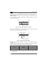
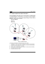
The cable connecting the base station to the PC has the following pinout:
2
3
9-pin connecto
r
(female)
1
RJ45 modular connector
PC side
STARGATE™ side
5 5
RX
TX
GND
2
Figure 7 - RS232 Pinout
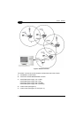
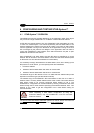
3.2 RS485 CONNECTION USING F904/N
Several STARGATE™ base stations can be chained together in an RS485 network
or a single STARGATE™ having a distance > 15 m from the PC can be connected.
The (first) base station is connected to the PC through an F904/N
RS232/485 converter set to the following default parameter values (see the F904/N
relevant manual for details):
− baud rate: 38400 bps
− data bits: 8
− parity: none
The power can be either individually supplied to each STARGATE™ present in the
system or propagated from one base station to another by means of a single power
supply (see Figure 10 and Figure 11 for further details).
9